After restarting software and saving the code it was bit different this time. Maybe the first one still used the old PP?
I took the code and changed the numbers to SAE and it no longer failed till the end.
There were 2 M codes on one line so I fixed that. test719.nc.txt (597 Bytes) test719 rev1.nc.txt (589 Bytes)
This now worked at least as a dry run so it is a start.
I think Centroid wants a M30 at the end too. It must not be to critical as I don’t see it in lots of other Centroid nc files, just in some doc from centroid.
There is some issues with the order of things as where it starts and stops and parks for tool change.
The spindle goes turns on and goes down to .2 above part and then moves to drill hole location. Should move first from Z home to drill feature then on and down.
There is also metric numbers in the software where there should be SAE and why is thou written out sometimes in some parameter choices? Am I missing some unit button someplace?
Listing such cases with the FreeCAD file would be helpful. You can include the G-code directly here in code tags (use the </> button!), that saves quite some clicks too.
OK. Learning best practices on your forum for sure.
I had posted the FC file a few posts back. Should I include that file most times when it would be relevant like this time? Same with the FC vers I am using? I did change the spindle speed and drill feeds. Other than that I think it was the same. I’ll send it again when I get to the shop.
I certainly don’t want to make it harder for you guys.
I did some other drawings and posted with the same results. MM instead of Inches. Inches are selected in units in preferences yet lots of reference to MM in combo view.
I add .1" but value sets +1mm
Also peck was not checked nor depth. Note the 97.500 Thou. Weird way to write instead of "
I get this in both drawings I am working on. I get the same warning whether I choose the bottom or top circle to drill.
Also note Edge5 depth is in MM?
I did not set feed rates yet so I understand that one.
09:47:13  Drilling Select Mode
09:47:13  op=Drilling (<class 'FeaturePython'>)
09:50:52  Free Select
10:01:50  Drilling Select Mode
10:01:50  op=Drilling (<class 'FeaturePython'>)
10:08:03  Free Select
10:08:03  op=Drilling (<class 'FeaturePython'>)
10:08:03  PathCircularHoleBase.WARNING: Verify Final Depth of holes based on edges. Edge5 depth is: 0.0 mm  Always select the bottom edge of the hole when using an edge.
10:08:03  PathOp.WARNING: Tool Controller feedrates required to calculate the cycle time.
new PP test.FCStd (90.9 KB)
I think getting the PP to post in inches is the biggest issue at this point.
Even the unconstrained, imported DXF will generate code now.
Not sure why it is all working now. It even generated with the old centroid_post.py but I didn’t compare. Just theory testing. cog centertest (3).FCStd (437 KB)
About the units,
setting preferences to Imperial decimal (in/lb) is working here. I recall unwanted results with some other setting but can’t remember which one..
It is difficult to follow your G-codes. If you don’t link or at least quote the post where the corresponding file is to be found. I tried to reproduce with the last FCStd file, but it shows something completely different.
IIRC I have derived the philips_post.py from centroid. So I guess I had it from there that not something like
… .append(param + format(c.Parameters[param], axis_precision_string))
was used, but rather
… .append(param + PostUtils.fmt(c.Parameters[param], AXIS_DECIMALS, UNITS))
Somehow this got lost, or I am mistaken and took it from somewhere else.
I am having no issues posting but the issues with metric code continues.
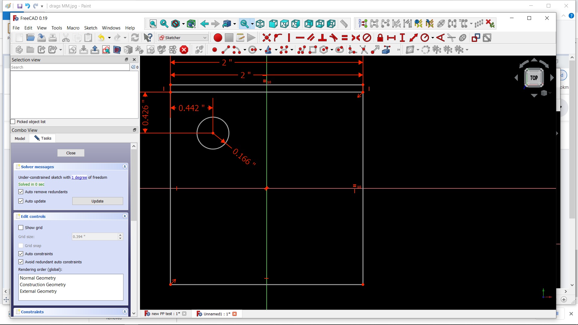
I am wondering if it isn’t the PP but the software and/or how I have it configured. I darkened the screen to see better and noticed while I drag a box from point to point and up, for example, the dimensions shown are in MM yet the drawing is in IN. 50.8 instead of 2" Could this be the causing my code issues?
If so I can move to different thread.
If you are seeing inches in the Sketcher, then your installation of FreeCAD is set up that way.
Check Edit >> Preferences >> General >> Units to make sure you have the unit system you want.
The FCStd file is always in metric only. Any other system is completely local to your installation and preferences. I use imperial, and every file I open from the forum (a lot!) shows dimensions in inches, even if the originator comes from one of those backward locations that uses metric.
I have tried both imperial and US, no change.
When you are creating a box, does the dimensions show in MM even when the drawing units are IN as the tiny white numbers at the top in the first photo in the previous post?
I just used the Mach PP and it also posts code in MM.
I don’t understand what you are referring to as “drawing units”. I do not recall ever seeing those tiny white numbers in any of my files.
FreeCAD is not 100% friendly to non-metric users, but about 99.99%. I always see only imperial numbers in the Sketcher. Most other numbers throughout FreeCAD are imperial for me, but occasionally on some task panel the numbers are in metric. No problem as I am fully conversant in either.
There is something wrong with your installation. In particular, your “user.cfg” file may be borked. You might tried removing that file (save a copy!!!) and let FreeCAD regenerate a new one.
In edit/preferences/general/units imperial or US. I have selected imperial.
I could barely see the little dimensions with the default screen. When I changed to black background I could then read those tiny numbers were in MM. THey only appear as you are dragging the feature to size.
I don’t have an issue with them, just trying to figure out why the post is in MM and not in IN.
I’m sure my package has issues as weird things happen and then they don’t like for ever when I started a drawing red lines appeared in the reports view panel. Then I posted pictures of it and then it stopped when I asked about it. 100 times doing the same simple drawing but couldn’t snap to intersects only points. Then I took a video of the process and it started working. Yesterday after a very rare reboot in the morn, all the tool bars disappeared in FC when I started it. Lost my tool library from both V19 and V18 which I never recovered. Then when I ran a new PP my son modified trying to get rid of the metric in posts I started getting red lines in reports. The PP works on his Linux machine. The old centroid one works as did MAch but the Dynapath one is all red and won’t post. There are many other anomalies I have, A page of them. I thought they all went away when I was finally able to post something till I restarted the computer yesterday.
I’m going to delete all versions and DL new files and start over again.
Is there a Reg Clean video or wiki? There is always trash left behind and it is bringing up info from previous install of 18.
FreeCAD does not use the registry for version 0.19, with two exceptions.
The QT package saves items like window placement in the registry.
Various shortcut links and auto-open links are stored in the registry. That is actually more of a Windows thing than FreeCAD.
FreeCAD does not store any preferences or design data in the registry. FreeCAD is not typically a “portable” package, but quite close. This makes sense, since the exact same code is compiled for many different operating systems.
The one big exception is that macros, user preferences, and a few other things (like postprocessors) are stored in the user storage location set up by the operating system. For Windows this will typically be C:\Users\your_user_id\AppData\Roaming\FreeCAD.
For installed versions of FreeCAD, such as the “stable” version 0.18, there will be additional junk in the registry related to the installer. But still nothing that impacts the actual operation of FreeCAD.
There should be no need for any sort of registry cleaner.
Good news and that explains the crossover between the installed 18 and when I open 19 and see my preferences. In 19 I didn’t have to scale the DXF import which it brought over from 18 if I recall. 1 worked fine with 19.
Wouldn’t running G21 instead of G20 work as far as machining goes? That would be a simple enough work around for now. I am rearranging things in the gcode as it is anyway being I can’t find a way to do it in the software yet or even if I can. One thing at a time.
Maybe this is my problem or did they make the file size smaller in less than a month? I have been using the older DL obviously.
I am not running it from this thumb drive.
Going to delete 18 on both computers, delete that FC folder C:\Users\your_user_id\AppData\Roaming\FreeCAD. and use this latest DL of 19 and hope.