It is customary to simply paste the information from “Help >> About FreeCAD >> Copy to clipboard” into the text of the message. No need for any tags. It is then completely visible without scrolling or any other manipulations. The lines are short and do not wrap.
If you look through the forum the overwhelming majority of folks do it the simple way.
There is a centroid simulator I have been using in the house. If it passes I go out to the shop. Simple load file and hit run. Shows tool path and can edit code.
During install, check demo offline. There is also Intercon which will generate code that you have to enter coordinates mostly that is in the software to get a idea of what Centroid asks for. I’m very happy with the Centroid Acorn control. https://www.centroidcnc.com/centroid_diy/downloads/acorn_cnc_software/centroid_acorn_cnc12_v4.5.zip
Like this? that’s easier, didn’t know you could paste clipboard to post.
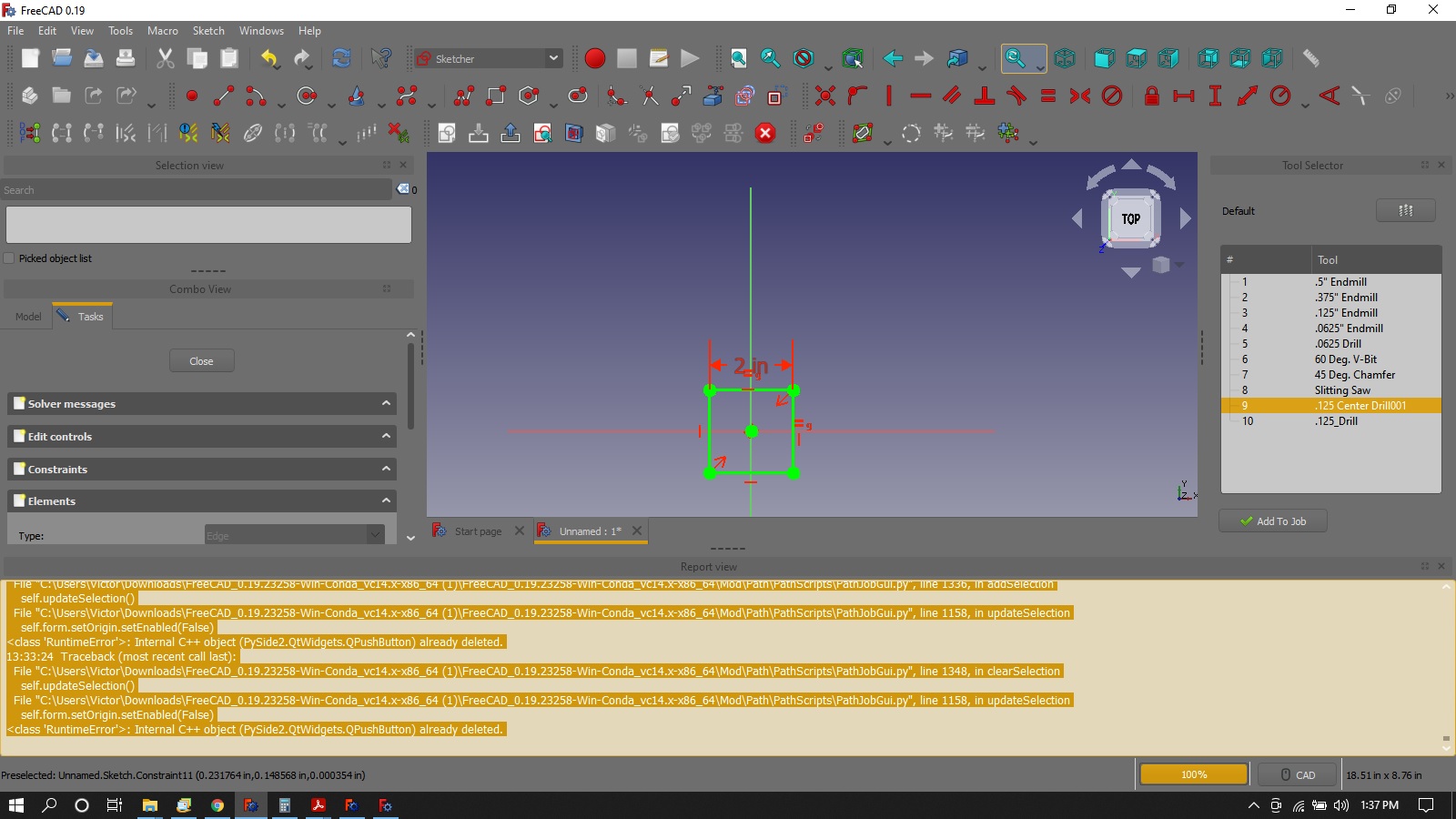
I’m betting it is the drawing with it’s lack of constraints?
I’m really learning so don’t assume it is software too quick. I’m putting in extremely long hours trying to get a handle on this and I’m sure I am messing things up pokin around so much and forgetting what I did.
I don’t recall doing anything weird with tool #9. I imported from my tool library. I did change the tool tip angle to 118 from 119 which I think was default. Never heard of a 119 deg drill bit.
Why would there be a horizontal move in a drill OP? Air movement?
OS: Windows 10 (10.0)
Word size of OS: 64-bit
Word size of FreeCAD: 64-bit
Version: 0.19.23258 (Git)
Build type: Release
Branch: master
Hash: 78c6cc1362c39e3f1f778c52ae2a1c82badeec20
Python version: 3.8.6
Qt version: 5.12.5
Coin version: 4.0.0
OCC version: 7.4.0
Locale: English/United States (en_US)
Not sure what you are referring to here. It does make sense for drill to move to next hole position, so this would be a horizontal air move (so you do not collide with your job or clamps). Is that what you mean?
I might add that I was able to inspect GCode and it passed my simulator but I don’t know why. Snowing now so I am not sure I will make it out to the shop tonight. test_nc.txt (1.4 KB)
This is a similar program I wrote in Intercon of the same part. hole pattern test intercon_cnc.txt (1.22 KB)
But that’s the centroid post processor again, not grbl - in order to use the grbl processor you need to change the setting in the Job.
Maybe I misunderstood, I thought you had said you get the same error with the grbl post processor.
I would of thought the horizontal move would be in a drill cycle in a macro after it goes to safe height. I can see telling the software to move horizontally at a certain speed after but just didn’t expect it there. G81 before each hole. I was afraid I was telling the drill to move while in the hole.
I don’t know GCode but am learning to understand somewhat.
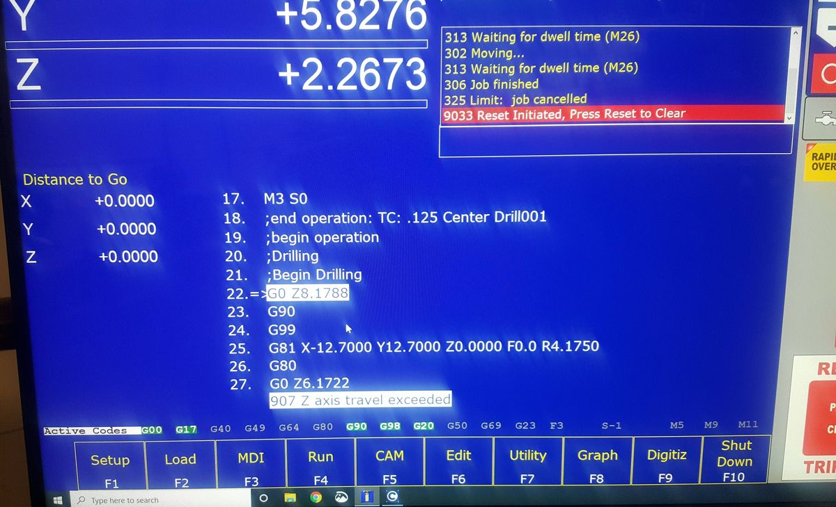
i Manned up and went to the shop.
That GCode doesn’t work. Didn’t think it would. Failed line 3, Z axis limit exceeded. DUH The simulator doesn’t know how much travel the machine has or where part zero is. Maybe I can further configure the Demo simulator. Back to the house and cozy fire and 60" monitor and continue to constrain.
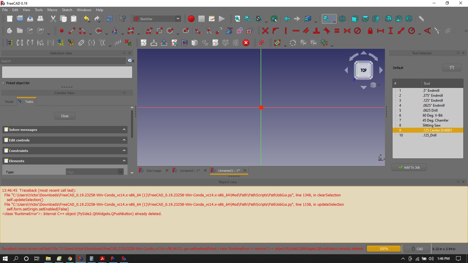
From the first start of the drawing the reports starts all red. Simple fully constrained from start. 2 hole test.FCStd (127 KB)
Still won’t save a GCode yet it processes one I can view but again don’t see how it would work. 2 hole test GCode preview.txt (238 Bytes)
report file Only a few black lines the rest are red from the first click. 2 hole test.txt (47.3 KB)
Can you tell what I am doing wrong? I’ve removed drilling op and no change when I added one back.
From the very first click in opening a new file from then on every click shows up in red in the report except when I select buttons like drill or simulate.
Can I see the GCode and part file please? I just don’t know what or how I could be so wrong on even simple as could be part.
LOL So I am not alone.
I tried to do something a 100 times and then setup to video the screen and ask for help and it worked. Can’t reproduce my error.
I have redrew in several different ways starting with sketcher and part design WB with one hole. Same results.
This is serious for me as I need centroid PP to post. I don’t want to go back to Bob but I did find a work around by deleting subprograms in the PP being there is no centroid one.
The centroid post needs work. I’m willing to help but I don’t have a centroid control to test on and don’t know exactly what the centroid will require.
Any centroid experts here want to help?
Let’s just start simple. I’ve fixed the error the proxy error that was occuring. It’s outputting gcode now. Can you test with this and tell me what’s missing?
I just saw a video from the start with the repots bar open.
Do you think this could be my issue?
All I did was open a drawing and hit the sketch button.
Everything I do is in red from now on
even with all the red I was FINALLY able to post to a file.
I tested in the house and no errors yet. Going to the shop. test.nc.txt (550 Bytes) errors.txt (23.1 KB)
Z axis limit exceeded. Looks like it is metric. I should of looked closer at the code. new PP test.FCStd (52.8 KB)