So this would not no longer use Sketch like currently ArchWindow does to generate shape right ?
"""
 FreeCAD script - macro
 to be used with the OnePartLib part library

 copyright 2019 Carlo Dormeletti (onekk)
 carlo.dormeletti@yahoo.com

 Version:

"""

import sys
import datetime
import time
import importlib

import FreeCAD
import FreeCADGui
from FreeCAD import Rotation, Vector
import Part
import Draft
#import Mesh
#import MeshPart

# BEGIN DOC Settings
DEBUG = True
DBG_LOAD = False
DOC_NAME = "finestra"
# END DOC settings


#from math import pi cos, sin, pi, sqrt
import numpy as np


def activate_doc():
    """activate document"""
    FreeCAD.setActiveDocument(DOC_NAME)
    FreeCAD.ActiveDocument = FreeCAD.getDocument(DOC_NAME)
    FreeCADGui.ActiveDocument = FreeCADGui.getDocument(DOC_NAME)
    if DBG_LOAD is True:
        print("{0} activated".format(DOC_NAME))


def setview():
    """Rearrange View"""
    DOC.recompute()
    VIEW.viewAxometric()
    VIEW.setAxisCross(True)
    VIEW.fitAll()


def clear_doc():
    """Clear the active document deleting all the objects"""
    for obj in DOC.Objects:
        DOC.removeObject(obj.Name)

if FreeCAD.ActiveDocument is None:
    FreeCAD.newDocument(DOC_NAME)
    if DBG_LOAD is True:
        print("Document: {0} Created".format(DOC_NAME))

# test if there is an active document with a "proper" name
if FreeCAD.ActiveDocument.Name == DOC_NAME:
    if DBG_LOAD is True:
        print("DOC_NAME exist")
else:
    if DBG_LOAD is True:
        print("DOC_NAME is not active")
    # test if there is a document with a "proper" name
    try:
        FreeCAD.getDocument(DOC_NAME)
    except NameError:
        if DBG_LOAD is True:
            print("No Document: {0}".format(DOC_NAME))
        FreeCAD.newDocument(DOC_NAME)
        if DBG_LOAD is True:
            print("Document {0} Created".format(DOC_NAME))

DOC = FreeCAD.getDocument(DOC_NAME)
GUI = FreeCADGui.getDocument(DOC_NAME)
VIEW = GUI.ActiveView
if DBG_LOAD is True:
    print("DOC : {0} GUI : {1}".format(DOC, GUI))

activate_doc()

if DBG_LOAD is True:
    print(FreeCAD.ActiveDocument.Name)

clear_doc()

EPS = 0.002

VZOR = Vector(0, 0, 0)
ROT0 = Rotation(0, 0, 0)
ROTX90 = Rotation(0, 0, 90)
ROTXN90 = Rotation(0, 0, -90)
ROTY90 = Rotation(0, 90, 0)
ROTZ180 = Rotation(180, 0, 0)
#Used to shorten most Placements
PL0 = FreeCAD.Placement(VZOR, ROT0)

# DOCUMENT START HERE

fin_h = 1400
fin_w = 1200
fin_th = 50
cont_w = 50
vetro_th = 3
vetro_add = 5

def telaio():
    e_tel_w = fin_w
    e_tel_h = fin_h
    i_tel_w = fin_w - cont_w * 2
    i_tel_h = fin_h - cont_w * 2
    v_w = i_tel_w + vetro_add * 2
    v_h = i_tel_h + vetro_add * 2

    ep0 = (e_tel_w * -0.5, 0, 0)
    ep1 = (e_tel_w * 0.5, 0, 0)
    ep2 = (e_tel_w * 0.5, 0, e_tel_h)
    ep3 = (e_tel_w * -0.5, 0, e_tel_h)

    ip0 = (i_tel_w * -0.5, 0, cont_w)
    ip1 = (i_tel_w * 0.5, 0, cont_w)
    ip2 = (i_tel_w * 0.5, 0, cont_w + i_tel_h)
    ip3 = (i_tel_w * -0.5, 0, cont_w + i_tel_h)

    vp0 = (v_w * -0.5, 0, cont_w - vetro_add)
    vp1 = (v_w * 0.5, 0, cont_w  - vetro_add)
    vp2 = (v_w * 0.5, 0, cont_w - vetro_add + v_h)
    vp3 = (v_w * -0.5, 0, cont_w - vetro_add + v_h)

    tel_b = (ep0, ep1, ip1, ip0, ep0)
    tel_bp = Part.makePolygon([Vector(*vtx) for vtx in tel_b])

    tel_r = (ep1, ep2, ip2, ip1, ep1)
    tel_rp = Part.makePolygon([Vector(*vtx) for vtx in tel_r])

    tel_t = (ep2, ep3, ip3, ip2, ep2)
    tel_tp = Part.makePolygon([Vector(*vtx) for vtx in tel_t])

    tel_l = (ep3, ep0, ip0, ip3, ep3)
    tel_lp = Part.makePolygon([Vector(*vtx) for vtx in tel_l])

    tel_fb = Part.makeFilledFace(tel_bp.Edges)
    tel_fbs = tel_fb.extrude(Vector(0, fin_th, 0))

    tel_fr = Part.makeFilledFace(tel_rp.Edges)
    tel_frs = tel_fr.extrude(Vector(0, fin_th, 0))

    tel_ft = Part.makeFilledFace(tel_tp.Edges)
    tel_fts = tel_ft.extrude(Vector(0, fin_th, 0))

    tel_fl = Part.makeFilledFace(tel_lp.Edges)
    tel_fls = tel_fl.extrude(Vector(0, fin_th, 0))

    vetro_pt = (vp0, vp1, vp2, vp3, vp0)
    vetro_p = Part.makePolygon([Vector(*vtx) for vtx in vetro_pt])

    vetro_f = Part.makeFilledFace(vetro_p.Edges)
    vetro_s = vetro_f.extrude(Vector(0, vetro_th, 0))
    vetro_s.Placement = FreeCAD.Placement(Vector(0, (fin_th - vetro_th) * 0.5, 0), ROT0)

    obj0 = DOC.addObject("Part::Feature", "telaio")
    obj0.Shape = Part.makeCompound((tel_fbs, tel_frs, tel_fts, tel_fls))
    obj0.ViewObject.ShapeColor = (0.54, 0.27, 0.07) # rgb(139, 69, 19)

    obj1 = DOC.addObject("Part::Feature", "vetro")
    obj1.Shape = vetro_s
    obj1.ViewObject.ShapeColor = (0.33, 0.67, 1.00)
    obj1.ViewObject.Transparency = 50

    obj_f = DOC.addObject("Part::Compound", "finestra")
    obj_f.Links = [obj0, obj1]

    return obj_f

telaio()
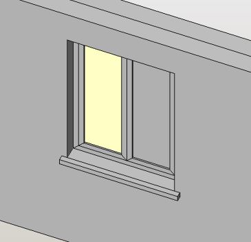
See if this is a good approach, I have returned the object as a compound made from the frame and the glass, in this compound we could add the sill and whatever we want, as a compound the colors are retained.
If you use my code, the axes are shown you will see that the window is created with the bottom center around Vector(0,0,0) and the window “extruding” by Y axes positive, seems to be a viable reference point, it lacks of the offset in y for the placement on the wall thickness and the sill dimensions (width length and thickness) to calculate the protrusion
#paulee no this is generating directly the shapes, draft object are returned as Part.Shapes with some additional properties.
Regards
Carlo D.
Nice! The compound is a good approach, but I’d like the default window shape to be completely embedded into the opening object (so we spare several objects in the final count). Basically it’s the Opening object that makes the final compound grouping the window and the sill (https://github.com/yorikvanhavre/BIM_Workbench/blob/b4b5d71b05e55b8eeb1758ab708907a667ec1e60/archobjects/opening.py#L47).
The “get_window_shape” should be called right here: https://github.com/yorikvanhavre/BIM_Workbench/blob/b4b5d71b05e55b8eeb1758ab708907a667ec1e60/archobjects/opening.py#L187
If you use my code, the axes are shown you will see that the window is created with the bottom center around Vector(0,0,0) and the window “extruding” by Y axes positive, seems to be a viable reference point, it lacks of the offset in y for the placement on the wall thickness and the sill dimensions (width length and thickness) to calculate the protrusion
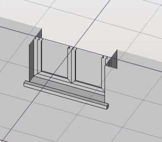
Hmm, I need the Placement.Base of the window in this red point:

@paullee, this is just a prototype for some default windows. Do not worry, I do not intend to loose the generation by sketch, but its slightly more complicated, so will come after ![]()
Thank, have fun ![]()
The compound is retaining the colors, if I don’t remember well if i fuse the object i will loose the colors and the ability to color the different faces, it is treated as a unique solid.
Let me see some more work, on the make the frame is only the external frame, now the opening part could be generated, 50mm for the frame and 50 mm for the opening simply “nested boxes” to reatin the seam each side has to be generated as a trapezoid.
More to come.
Regards
Carlo D.
great, have fun!
"""
 FreeCAD script - macro
 to be used with the OnePartLib part library

 copyright 2019 Carlo Dormeletti (onekk)
 carlo.dormeletti@yahoo.com

 Version:

"""

import sys
import datetime
import time

import FreeCAD
import FreeCADGui
from FreeCAD import Rotation, Vector
import Part
import Draft
#import Mesh
#import MeshPart

# BEGIN DOC Settings
DEBUG = True
DBG_LOAD = False
DOC_NAME = "finestra"
# END DOC settings


#from math import pi cos, sin, pi, sqrt
import numpy as np


def activate_doc():
    """activate document"""
    FreeCAD.setActiveDocument(DOC_NAME)
    FreeCAD.ActiveDocument = FreeCAD.getDocument(DOC_NAME)
    FreeCADGui.ActiveDocument = FreeCADGui.getDocument(DOC_NAME)
    if DBG_LOAD is True:
        print("{0} activated".format(DOC_NAME))


def setview():
    """Rearrange View"""
    DOC.recompute()
    VIEW.viewAxometric()
    VIEW.setAxisCross(True)
    VIEW.fitAll()


def clear_doc():
    """Clear the active document deleting all the objects"""
    for obj in DOC.Objects:
        DOC.removeObject(obj.Name)

if FreeCAD.ActiveDocument is None:
    FreeCAD.newDocument(DOC_NAME)
    if DBG_LOAD is True:
        print("Document: {0} Created".format(DOC_NAME))

# test if there is an active document with a "proper" name
if FreeCAD.ActiveDocument.Name == DOC_NAME:
    if DBG_LOAD is True:
        print("DOC_NAME exist")
else:
    if DBG_LOAD is True:
        print("DOC_NAME is not active")
    # test if there is a document with a "proper" name
    try:
        FreeCAD.getDocument(DOC_NAME)
    except NameError:
        if DBG_LOAD is True:
            print("No Document: {0}".format(DOC_NAME))
        FreeCAD.newDocument(DOC_NAME)
        if DBG_LOAD is True:
            print("Document {0} Created".format(DOC_NAME))

DOC = FreeCAD.getDocument(DOC_NAME)
GUI = FreeCADGui.getDocument(DOC_NAME)
VIEW = GUI.ActiveView
if DBG_LOAD is True:
    print("DOC : {0} GUI : {1}".format(DOC, GUI))

activate_doc()

if DBG_LOAD is True:
    print(FreeCAD.ActiveDocument.Name)

clear_doc()

EPS = 0.002

VZOR = Vector(0, 0, 0)
ROT0 = Rotation(0, 0, 0)
ROTX90 = Rotation(0, 0, 90)
ROTXN90 = Rotation(0, 0, -90)
ROTY90 = Rotation(0, 90, 0)
ROTZ180 = Rotation(180, 0, 0)
#Used to shorten most Placements
PL0 = FreeCAD.Placement(VZOR, ROT0)

# DOCUMENT START HERE

def telaio(tel_name, tel_w, tel_h , tel_ww, tel_wh, tel_th, et=0):
    i_tel_w = tel_w - tel_ww * 2
    i_tel_h = tel_h - tel_wh * 2

    if et == 0:
        ofz = 0
    else:
        ofz = tel_wh

    ep0 = (tel_w * -0.5, 0, ofz)
    ep1 = (tel_w * 0.5, 0, ofz)
    ep2 = (tel_w * 0.5, 0, tel_h + ofz)
    ep3 = (tel_w * -0.5, 0, tel_h + ofz)

    ip0 = (i_tel_w * -0.5, 0, tel_ww + ofz)
    ip1 = (i_tel_w * 0.5, 0, tel_ww + ofz)
    ip2 = (i_tel_w * 0.5, 0, tel_ww + i_tel_h + ofz)
    ip3 = (i_tel_w * -0.5, 0, tel_ww + i_tel_h + ofz)

    tel_b = (ep0, ep1, ip1, ip0, ep0)
    tel_bp = Part.makePolygon([Vector(*vtx) for vtx in tel_b])

    tel_r = (ep1, ep2, ip2, ip1, ep1)
    tel_rp = Part.makePolygon([Vector(*vtx) for vtx in tel_r])

    tel_t = (ep2, ep3, ip3, ip2, ep2)
    tel_tp = Part.makePolygon([Vector(*vtx) for vtx in tel_t])

    tel_l = (ep3, ep0, ip0, ip3, ep3)
    tel_lp = Part.makePolygon([Vector(*vtx) for vtx in tel_l])

    tel_fb = Part.makeFilledFace(tel_bp.Edges)
    tel_fbs = tel_fb.extrude(Vector(0, tel_th, 0))

    tel_fr = Part.makeFilledFace(tel_rp.Edges)
    tel_frs = tel_fr.extrude(Vector(0, tel_th, 0))

    tel_ft = Part.makeFilledFace(tel_tp.Edges)
    tel_fts = tel_ft.extrude(Vector(0, tel_th, 0))

    tel_fl = Part.makeFilledFace(tel_lp.Edges)
    tel_fls = tel_fl.extrude(Vector(0, tel_th, 0))

    obj0 = DOC.addObject("Part::Feature", tel_name)
    obj0.Shape = Part.makeCompound((tel_fbs, tel_frs, tel_fts, tel_fls))
    obj0.ViewObject.ShapeColor = (0.54, 0.27, 0.07) # rgb(139, 69, 19)

    return obj0


def finestra(opening_th=300, opening_height=1400, opening_width=1200,
             frame_width=50, frame_th=50, glass_th=21):
    vetro_add = 5
    # permit to differentiate from the top-bottom
    # and left right
    frame_height = frame_width
    cont_w = frame_width * 2
    cont_h = frame_height * 2

    ea_w = opening_width - cont_w
    ea_h = opening_height - cont_h

    v_w = ea_w - cont_w + vetro_add * 2
    v_h = ea_h - cont_h + vetro_add * 2

    vp0 = (v_w * -0.5, 0, cont_w - vetro_add)
    vp1 = (v_w * 0.5, 0, cont_w  - vetro_add)
    vp2 = (v_w * 0.5, 0, cont_h - vetro_add + v_h)
    vp3 = (v_w * -0.5, 0, cont_h - vetro_add + v_h)

    vetro_pt = (vp0, vp1, vp2, vp3, vp0)
    vetro_p = Part.makePolygon([Vector(*vtx) for vtx in vetro_pt])

    vetro_f = Part.makeFilledFace(vetro_p.Edges)
    vetro_s = vetro_f.extrude(Vector(0, glass_th, 0))
    vetro_s.Placement = FreeCAD.Placement(Vector(0, (frame_th - glass_th) * 0.5, 0), ROT0)

    obj_t = telaio("telaio", opening_width, opening_height, frame_width,
                   frame_height, frame_th, 0)

    obj_ea = telaio("elemento apribile", ea_w, ea_h, frame_width,
                   frame_height, frame_th, 1)

    obj1 = DOC.addObject("Part::Feature", "vetro")
    obj1.Shape = vetro_s
    obj1.ViewObject.ShapeColor = (0.33, 0.67, 1.00)
    obj1.ViewObject.Transparency = 50

    obj_f = DOC.addObject("Part::Compound", "finestra")
    obj_f.Links = [obj_t, obj_ea, obj1]

    return obj_f

finestra()


setview()
Here the new version, more parametric, let me know what other dimensions you need, it create three elements, the frame the open element and the glass (one box of 21mm thickness tunable in the method call)
As I’have no opening object i have chosen to make all the dimensions explicit, there is provision for a different horizontal frame_height differentiate from the vertical elements
The frame is created byu the same routine, adding an offset value, of frame_height (the heigh of horizontal element).
I hope this combine flexibility and speed, as I have not used primitives, but created objects individually i hope the speed will be not a problem, as only the final elements are created as docObjects.
From my point of view the only things that lacks is the offset Y (the distance from the outer side of the wall to “position” the window).
Just ion case we could add some other things, like the glass stopper, but i think that it will be an unuseful addition.
Maybe we could define one or two “open element” half of the width of the resulting frame.
What do you think
Regards
Carlo D.
I think that this is cool!

I like that you created a frame object that we can use multiple times inside the window! (edit: i stressed it a bit ad it seems quite fast!)
I modified it slightly to make it return a shape instead of creating a document object.
From my point of view the only things that lacks is the offset Y (the distance from the outer side of the wall to “position” the window).
In my idea this will be handled by the Opening object. (I already setted up the properties FillingAlignment and FillingDisplacement, I still miss the logic, but won’t be difficult to implement).
For the colors I have to check how Draft_Clone does it. But I think that it could be feasible also grouping everything inside just one shape.
The prototype is inside BIM workbench experimental tools since … NOW!
We could think about different presets… for example we could define how many panes the window should have (1-2-3-10?)
Thanks
Not to reinvent the wheel, if i reuse my code and add a number of panes in :
def finestra(opening_th=300, opening_height=1400, opening_width=1200,
             frame_width=50, frame_th=50, glass_th=21, n_pan=1):
let me see if i caould put in place something.
For the sill, it have to be under the “opening” so the sill is flush with the opening partially overlap it and protrude slighlty outwards.
I could do some coding.
But lateral and top sills like is usually seen in some region of Italy (and also in Europe), or maybe we are doing too much.
Regards
Carlo D.
Great!
For the sill, it should not overlap with the opening but with the wall, so if we have 100x150cm opening, after adding the sill the measures are still ok.
I was thinking about adding a Bool flag “subtract also positive shapes from the wall”, so we can easily manage to have sills and windows overlapping with the wall, or bigger than the opening itself, as it often is in the reality.
Having the whole stone frame of the opening should be considered as well as the standard bottom sill, they can be 2 different options perhaps!
What do you think?
OK there is my code, only the relevant part.
# DOCUMENT START HERE

def telaio(tel_w, tel_h , tel_ww, tel_wh, tel_th):
    i_tel_w = tel_w - tel_ww * 2
    i_tel_h = tel_h - tel_wh * 2

    ep0 = (tel_w * -0.5, 0, 0)
    ep1 = (tel_w * 0.5, 0, 0)
    ep2 = (tel_w * 0.5, 0, tel_h)
    ep3 = (tel_w * -0.5, 0, tel_h)

    ip0 = (i_tel_w * -0.5, 0, tel_ww)
    ip1 = (i_tel_w * 0.5, 0, tel_ww)
    ip2 = (i_tel_w * 0.5, 0, tel_ww + i_tel_h)
    ip3 = (i_tel_w * -0.5, 0, tel_ww + i_tel_h)

    tel_b = (ep0, ep1, ip1, ip0, ep0)
    tel_bp = Part.makePolygon([Vector(*vtx) for vtx in tel_b])

    tel_r = (ep1, ep2, ip2, ip1, ep1)
    tel_rp = Part.makePolygon([Vector(*vtx) for vtx in tel_r])

    tel_t = (ep2, ep3, ip3, ip2, ep2)
    tel_tp = Part.makePolygon([Vector(*vtx) for vtx in tel_t])

    tel_l = (ep3, ep0, ip0, ip3, ep3)
    tel_lp = Part.makePolygon([Vector(*vtx) for vtx in tel_l])

    tel_fb = Part.makeFilledFace(tel_bp.Edges)
    tel_fbs = tel_fb.extrude(Vector(0, tel_th, 0))

    tel_fr = Part.makeFilledFace(tel_rp.Edges)
    tel_frs = tel_fr.extrude(Vector(0, tel_th, 0))

    tel_ft = Part.makeFilledFace(tel_tp.Edges)
    tel_fts = tel_ft.extrude(Vector(0, tel_th, 0))

    tel_fl = Part.makeFilledFace(tel_lp.Edges)
    tel_fls = tel_fl.extrude(Vector(0, tel_th, 0))

    return (tel_fbs, tel_frs, tel_fts, tel_fls)


def vetro(ea_w, ea_h, ef_w, ef_h, v_a, frame_th, glass_th):
    v_w = ea_w - ef_w + v_a * 2
    v_h = ea_h - ef_h + v_a * 2

    vp0 = (v_w * -0.5, 0, ef_w - v_a)
    vp1 = (v_w * 0.5, 0, ef_w  - v_a)
    vp2 = (v_w * 0.5, 0, ef_h - v_a + v_h)
    vp3 = (v_w * -0.5, 0, ef_h - v_a + v_h)

    vetro_pt = (vp0, vp1, vp2, vp3, vp0)
    vetro_p = Part.makePolygon([Vector(*vtx) for vtx in vetro_pt])

    vetro_f = Part.makeFilledFace(vetro_p.Edges)
    vetro_s = vetro_f.extrude(Vector(0, glass_th, 0))

    return vetro_s

def finestra(opening_th=300, opening_height=1400, opening_width=1200,
             frame_width=50, frame_th=50, glass_th=21, n_pan=1):
    # permit to differentiate from the top-bottom
    # and left right
    frame_height = frame_width

    # congruency check:
    frame_ov_wid = n_pan * (frame_width * 2) + frame_width * 2

    light_fact = (opening_width - frame_ov_wid) / opening_width
    #print("FW LF >",frame_ov_wid, light_fact)

    # TODO Adapt the warning to FreeCAD warning standard
    if  light_fact < 0.40 :
        print("Too Many panes in the window resulting in < 40% of the opening")
        return

    objs = telaio(opening_width, opening_height, frame_width,
                   frame_height, frame_th)

    # NOTE: non need for a placement is build on center
    obj_t = DOC.addObject("Part::Feature", "telaio")
    obj_t.Shape = Part.makeCompound(objs)
    obj_t.ViewObject.ShapeColor = (0.54, 0.27, 0.07) # rgb(139, 69, 19)

    cmps = [obj_t]

    # frame reduction
    ef_w = frame_width * 2
    ef_h = frame_height * 2

    res_w = opening_width - ef_w
    res_h = opening_height - ef_h

    # glass margin into the frame
    v_a = 5

    if n_pan == 1:
        ea_w = res_w
        ea_h = res_h

        objs = telaio(ea_w, ea_h, frame_width,  frame_height, frame_th)

        # NOTE: we must displace this object only in vertical
        pl_ea = FreeCAD.Placement(Vector(0, 0, frame_height), ROT0)

        obj_ea = DOC.addObject("Part::Feature", "elemento apribile")
        obj_ea.Shape = Part.makeCompound(objs)
        obj_ea.Placement = pl_ea

        # ViewObject part
        obj_ea.ViewObject.ShapeColor = (0.54, 0.27, 0.07) # rgb(139, 69, 19)

        cmps.append(obj_ea)

        vetro_s = vetro(ea_w, ea_h, ef_w, ef_h, v_a, frame_th, glass_th)

        pl_v = FreeCAD.Placement(Vector(0, (frame_th - glass_th) * 0.5, 0), ROT0)
        obj_v = DOC.addObject("Part::Feature", "vetro")
        obj_v.Shape = vetro_s
        obj_v.Placement = pl_v

        # ViewObject part
        obj_v.ViewObject.ShapeColor = (0.33, 0.67, 1.00)
        obj_v.ViewObject.Transparency = 50

        cmps.append(obj_v)

    elif n_pan > 1 and n_pan < 10:
        # just in case someone entered an absurd number
        fact_w = res_w / n_pan

        loop = True
        cnt = 1
        while loop is True:
            if cnt > n_pan:
                break
            ea_w = fact_w
            adv_x = (cnt - 1) * fact_w
            ofx = (res_w * -0.5) + fact_w * 0.5 + adv_x
            ea_h = res_h

            objs = telaio(ea_w, ea_h, frame_width,  frame_height, frame_th)
            # NOTE: we must displace this object in both direction
            pl_ea = FreeCAD.Placement(Vector(ofx, 0, frame_height), ROT0)

            obj_ea = DOC.addObject("Part::Feature", "e_a_" + str(cnt))
            obj_ea.Shape = Part.makeCompound(objs)
            obj_ea.Placement = pl_ea
            obj_ea.ViewObject.ShapeColor = (0.54, 0.27, 0.07) # rgb(139, 69, 19)

            cmps.append(obj_ea)

            vetro_s = vetro(ea_w, ea_h, ef_w, ef_h, v_a, frame_th, glass_th)

            pl_v = FreeCAD.Placement(Vector(ofx, (frame_th - glass_th) * 0.5, 0), ROT0)
            obj_v = DOC.addObject("Part::Feature", "ve_" + str(cnt))
            obj_v.Shape = vetro_s
            obj_v.Placement = pl_v
            obj_v.ViewObject.ShapeColor = (0.33, 0.67, 1.00)
            obj_v.ViewObject.Transparency = 50

            cmps.append(obj_v)

            cnt += 1

    obj_f = DOC.addObject("Part::Compound", "finestra")
    obj_f.Links = cmps

    return obj_f

finestra(300, 1400, 1200, 50, 50, 21, 6)

setview()
Now the intermediate methods return the TopoShape only, the solid creation is done in the main part.
Note that I’ve moved the placement to permit the reuse of the frame creation method,
I have tested it.
I have added a simple check of congruence if too many windows panels are selected I have put a limit of 40% of the opening_width that has to be left for the glass, I don’t know if it is a good thing, but it could be a sane check, i have tested and seems a decent choice.
A side effect is that from the way i have done in the multi panes part a value of n_pan = 0 will output only the frame, maybe this could be good for someone.
Take care if you adapt the code of the placement thing.
Working on integrating the sill, but for this the how to deal with opening thickness, in building the sill is placed taking into account the frame position that is not always flush with the interior of the wall (at least for the brick walls that are the normal building technique in Italy).
I have done a quick look at the code, but many of my construct are not to be put in the final code, the preamble part of my code
when creating and checking the documents and so on.
Regards
Carlo D.
Seems good!
I have added a simple check of congruence if too many windows panels are selected I have put a limit of 40% of the opening_width that has to be left for the glass, I don’t know if it is a good thing, but it could be a sane check, i have tested and seems a decent choice
Seems good too. Hope to find the time to test it tomorrow…
Working on integrating the sill, but for this the how to deal with opening thickness, in building the sill is placed taking into account the frame position that is not always flush with the interior of the wall (at least for the brick walls that are the normal building technique in Italy).
That’s true. I see 2 possibilities. 1 just don’t care about that. 2 make it slightly shorter and subtract the sill from the wall…
In the first option we would have to adjust the wall standard subtraction… Don’t know if this is good… @Yorik, what do you think?
I have done a quick look at the code, but many of my construct are not to be put in the final code, the preamble part of my code
when creating and checking the documents and so on.
Sure, I just merged to show you where it would likely go! ![]()
Cheers!
Very nice!
It works really good ![]()
Mind that the glass is a bit bigger than what expected. It’s good in the reality, but it cause to miss one visible edge in the drawing, so i’d suggest to make it exactly the size of the inner frame. What do you think?
I think the window should provide the exact shape that must be subtracted, the wall itself shouldn’t care about more complicated scenarios. Otherwise very quickly it will grow extra complicated.
Yes, definitely, at the moment the wall asks the opening for opening.get_void_shape(opening) and the opening returns the exact shape to be subtracted.
Of course the opening can do the same with the window, and return to the wall the final void shape, so get_void_shape will return not just a Part::Box, but also the shape of the window frame and of the sill, in case they are embedded into the wall…
Do you think it’s correct?
Edit, a quick sketch to clarify it:

Edit2: @yorik, is it good if I start every commit to BIM wb with Arch: prefix?
just modify this value:
    # glass margin into the frame
    v_a = 5
with 0 if i have done the calculation right the glass will be flush with the frame.
Regards
Carlo D.
Yeah!
Fro the sill, the only vlue needed for now are for the protruding part, sides lenght, and front length plus, the thickness:
 sill_wid = opening.width + sides_length * 2
 sill_th = <desidered value>
 sill_len = wall_thickness * 0.95  + protruding length
 obj = Part.makeBox(sill_len, sill_wid, sill_th)
 obj.Placement = FreeCAD.Placement(Vector(sill_wid * -0.5, wall_thick * -0.95 , sil_th * -1), ROT0)
Hope the calculation are right, No need to calculate some complex form, the object is embedded in the wall under the central reference point.
The 0.95 factor maybe could be 0.99.
Regards
Carlo D.
Nice! Just integrated the multi-pane window, and it works really good. Now I have to think about how the user is supposed to interact with it: will we have a multiple choice like “Default Window Single pane”, “Default Window Double pane”, “Default Window Triple pane”? will we have just one “Default window” choice, and when chosen 2 or more properties will appear allowing the user to tweak the default window?
For the sill, I’d prefer to not rely on a simple Part Box. In 3d it’s enough, but if we switch to a 2d section and cut the wall, if we do not cap the cutted faces, we will see the overlapping part:

If instead we use a T extruded shape for the sill, it will result in a correct orizontal section view. What do you think?
Edit: this is the modified code, integrated into the BIM WB! I changed some strings to english and added some docstrings too. (Also removed the document object creation part, since we need to return a shape to the opening object)
#***************************************************************************
#*  Copyright (c) 2020 Carlo Dormeletti (onekk) carlo.dormeletti@yahoo.com *
#*                                                                         *
#*  This program is free software; you can redistribute it and/or modify   *
#*  it under the terms of the GNU Lesser General Public License (LGPL)     *
#*  as published by the Free Software Foundation; either version 2 of      *
#*  the License, or (at your option) any later version.                    *
#*  for detail see the LICENCE text file.                                  *
#*                                                                         *
#*  This program is distributed in the hope that it will be useful,        *
#*  but WITHOUT ANY WARRANTY; without even the implied warranty of         *
#*  MERCHANTABILITY or FITNESS FOR A PARTICULAR PURPOSE.  See the          *
#*  GNU Library General Public License for more details.                   *
#*                                                                         *
#*  You should have received a copy of the GNU Library General Public      *
#*  License along with this program; if not, write to the Free Software    *
#*  Foundation, Inc., 59 Temple Place, Suite 330, Boston, MA  02111-1307   *
#*  USA                                                                    *
#*                                                                         *
#***************************************************************************
"""Provide the window presets to be used in the Arch Opening object
"""
## @package window_presets
# \ingroup ARCH
# \brief Provide the window presets to be used in the Arch Opening object.

import FreeCAD
import FreeCADGui
from FreeCAD import Rotation, Vector

App = FreeCAD

# BEGIN DOC Settings
DEBUG = True
DBG_LOAD = False
DOC_NAME = "finestra"
# END DOC settings

EPS = 0.002

VZOR = App.Vector(0, 0, 0)
ROT0 = App.Rotation(0, 0, 0)
ROTX90 = App.Rotation(0, 0, 90)
ROTXN90 = App.Rotation(0, 0, -90)
ROTY90 = App.Rotation(0, 90, 0)
ROTZ180 = App.Rotation(180, 0, 0)
#Used to shorten most Placements
PL0 = App.Placement(VZOR, ROT0)

# DOCUMENT START HERE

# ++++++++++++++++++++++++++++++++++++++++++++++++++++++++++++++++++ Components

def frame_rectangular(tel_w, tel_h , tel_ww, tel_wh, tel_th, et=0):
    """ Return the shape of a rectangular frame.
    """
    import Part

    i_tel_w = tel_w - tel_ww * 2
    i_tel_h = tel_h - tel_wh * 2

    ep0 = (tel_w * -0.5, 0, 0)
    ep1 = (tel_w * 0.5, 0, 0)
    ep2 = (tel_w * 0.5, 0, tel_h)
    ep3 = (tel_w * -0.5, 0, tel_h)

    ip0 = (i_tel_w * -0.5, 0, tel_ww)
    ip1 = (i_tel_w * 0.5, 0, tel_ww)
    ip2 = (i_tel_w * 0.5, 0, tel_ww + i_tel_h)
    ip3 = (i_tel_w * -0.5, 0, tel_ww + i_tel_h)

    tel_b = (ep0, ep1, ip1, ip0, ep0)
    tel_bp = Part.makePolygon([Vector(*vtx) for vtx in tel_b])

    tel_r = (ep1, ep2, ip2, ip1, ep1)
    tel_rp = Part.makePolygon([Vector(*vtx) for vtx in tel_r])

    tel_t = (ep2, ep3, ip3, ip2, ep2)
    tel_tp = Part.makePolygon([Vector(*vtx) for vtx in tel_t])

    tel_l = (ep3, ep0, ip0, ip3, ep3)
    tel_lp = Part.makePolygon([Vector(*vtx) for vtx in tel_l])

    tel_fb = Part.makeFilledFace(tel_bp.Edges)
    tel_fbs = tel_fb.extrude(Vector(0, tel_th, 0))

    tel_fr = Part.makeFilledFace(tel_rp.Edges)
    tel_frs = tel_fr.extrude(Vector(0, tel_th, 0))

    tel_ft = Part.makeFilledFace(tel_tp.Edges)
    tel_fts = tel_ft.extrude(Vector(0, tel_th, 0))

    tel_fl = Part.makeFilledFace(tel_lp.Edges)
    tel_fls = tel_fl.extrude(Vector(0, tel_th, 0))

    return Part.makeCompound([tel_fbs, tel_frs, tel_fts, tel_fls])


def glass(ea_w, ea_h, ef_w, ef_h, v_a, frame_th, glass_th):
    """Return the shape of a rectangular glass panel.
    TODO: Check if a Part::Box is faster
    """
    import Part

    v_w = ea_w - ef_w + v_a * 2
    v_h = ea_h - ef_h + v_a * 2

    vp0 = (v_w * -0.5, 0, ef_w - v_a)
    vp1 = (v_w * 0.5, 0, ef_w  - v_a)
    vp2 = (v_w * 0.5, 0, ef_h - v_a + v_h)
    vp3 = (v_w * -0.5, 0, ef_h - v_a + v_h)

    glass_pt = (vp0, vp1, vp2, vp3, vp0)
    glass_p = Part.makePolygon([Vector(*vtx) for vtx in glass_pt])

    glass_f = Part.makeFilledFace(glass_p.Edges)
    glass_s = glass_f.extrude(Vector(0, glass_th, 0))

    return glass_s


def default_sill(opening_width, host_thickness, sill_thickness, front_protrusion, lateral_protrusion, inner_covering):
    """Return the shape of a rectangular glass panel.
    TODO: Check if a Part::Box is faster
    """
    import Part

    sill_wid = opening_width + lateral_protrusion * 2
    sill_th = sill_thickness
    sill_len = host_thickness + front_protrusion - inner_covering
    sill = Part.makeBox(sill_wid, sill_len, sill_th)
    sill.Placement.Base = Vector(sill_wid * -0.5, host_thickness * -0.5 + inner_covering , sill_thickness * -1)

    return sill

# +++++++++++++++++++++++++++++++++++++++++++++++++++++++++++++++++++++ Windows

def window_single_pane(opening_th=300, opening_height=1400, opening_width=1200,
             frame_width=50, frame_th=50, glass_th=21, n_pan=1):
    """Return the shape of a full n_panes rectangular window.
    """
    import Part

    # permit to differentiate from the top-bottom and left right
    frame_height = frame_width

    # congruency check:
    frame_ov_wid = n_pan * (frame_width * 2) + frame_width * 2

    light_fact = (opening_width - frame_ov_wid) / opening_width
    #print("FW LF >",frame_ov_wid, light_fact)

    # frame reduction
    ef_w = frame_width * 2
    ef_h = frame_height * 2

    res_w = opening_width - ef_w
    res_h = opening_height - ef_h

    # glass margin into the frame
    v_a = 0

    # TODO Adapt the warning to FreeCAD warning standard
    if  light_fact < 0.40 :
        print("Too Many panes in the window resulting in < 40% of the opening")
        return

    # CREATE COMPONENTS
    components = []

    # CREATE FIXED FRAME
    components.append(frame_rectangular(opening_width, opening_height, frame_width,
                   frame_height, frame_th))

    # CREATE OPENING PANELS
    if n_pan == 0:
        # TODO: If n_pan == 0 create a fixed window
        return

    if n_pan == 1:
        # Create a single pane window
        ea_w = res_w
        ea_h = res_h

        open_frame = frame_rectangular(ea_w, ea_h, frame_width,  frame_height, frame_th)
        open_frame.Placement = FreeCAD.Placement(Vector(0, 0, frame_height), ROT0)
        components.append(open_frame)

        glass_s = glass(ea_w, ea_h, ef_w, ef_h, v_a, frame_th, glass_th)
        pl_v = FreeCAD.Placement(Vector(0, (frame_th - glass_th) * 0.5, 0), ROT0)
        glass_s.Placement = pl_v

        components.append(glass_s)

    elif n_pan > 1 and n_pan < 10:
        # Create a multi pane window
        fact_w = res_w / n_pan

        loop = True
        cnt = 1
        while loop is True:
            if cnt > n_pan:
                break
            ea_w = fact_w
            adv_x = (cnt - 1) * fact_w
            ofx = (res_w * -0.5) + fact_w * 0.5 + adv_x
            ea_h = res_h

            open_frame = frame_rectangular(ea_w, ea_h, frame_width,  frame_height, frame_th)
            pl_ea = FreeCAD.Placement(Vector(ofx, 0, frame_height), ROT0)
            open_frame.Placement = pl_ea

            components.append(open_frame)

            glass_s = glass(ea_w, ea_h, ef_w, ef_h, v_a, frame_th, glass_th)
            pl_v = FreeCAD.Placement(Vector(ofx, (frame_th - glass_th) * 0.5, 0), ROT0)
            glass_s.Placement = pl_v

            components.append(glass_s)

            cnt += 1

    window = Part.makeCompound(components)

    return window
Here a small experiment of what seems to me the best way to handle custom properties for the filling element!