First of all, many thanks to realthunder for providing the base object to play around and to yorik for accepting the tools into the BIM Workbench!
I’d like report into this topic the updates to my experiments with a kind of “Assembly” approach to BIM modelling, in the hope it can improve the current modelling experience. This also go into the direction to address last year discussion about separating semantics and representation of construction elements (profile extrusion vs wall) as Ifc try to.
Experimental Arch tools are available in the BIM workbench, if you like to try them out and give me a feedback it would be really appreciated!
At the moment the available tools are:
a Wall object that can be parametrically auto-joined with other walls as well as embed any kind of shape;
an Opening object: that can represent a void or embed a window or a door;
an ArchView object: that provides the infrastructure for 2d section drawing and it’s based on current Arch.SectionPlane, Draft.WorkingPlaneProxy and Draft.Shape2dView objects.
The rest of the topic follow the many try and errors I encountered during the development process so it may be quite boring to read, but i leave to you the decision
This is ideed good, and if we find interesting to evaluate the possibility to invest on the approach i’m proposing, I’d like to support Arch-sketch, but in a different way:
I’d like every wall segment to be indipendent and bound to just one sketch sub element.
I’d like every window to be inserted into the wall.
So the wall will be the same if it’s bound to a sketch element or on a wall-trace or just do not have a base object.
Anyway I still do not have it clear… I’d like others to jump into the discussion (also to say that it’s everything wrong)
And this is what I have in mind for the super basic wall without BaseGeometry.
It’s a Part Wedge, where the splay is controlled by an angle. This angle can be automatically calculated according to the the wall it have to join.
EDIT: Thinking about it: Also the simple wall object should not have it’s geometry generation implicit! It’s better that the wall will just perform boolean operations on linked children. So also creating the most simple wall, will produce the wall container and a child WallShape object. This will keep everything really plain and clear.
That can be easily automated to match the joined wall seamlessly…
EDIT: thinking about this tonight. This is not the right approach. The wall should be dumb instead, and I think we need another object, a kind of solver to compute the wall joinings and to keep track of them, so we do not run into circular dependencies. The user will move the wall, and then recompute the wall joints… Let’s see!
A small attempt to imagine how the user will work with the wall: he can toggle the display mode (we should find a good name to define it, ?Toggle wall compound/components?) and move graphically the childrens, later he can toggle it again and go back to the whole wall compound.
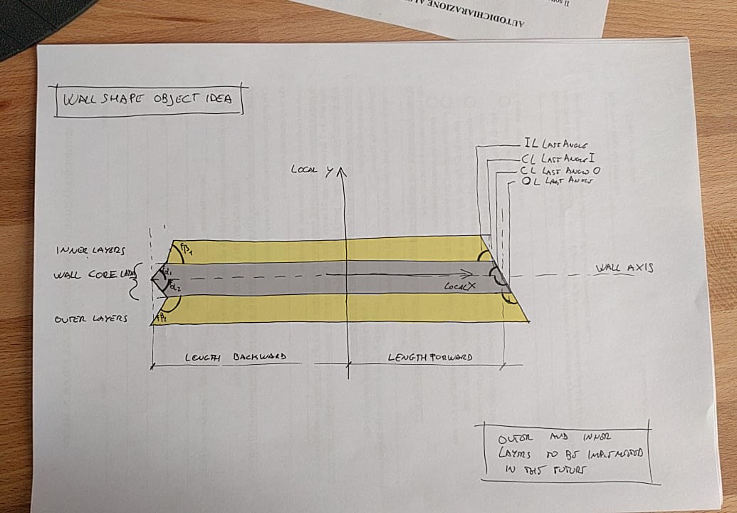
And here you have a first idea of the most basic wall Object to be linked to the BaseGeometry property. (By the way, this could be driven by a sketch segment, but i don’t want to mess up the current wall geometry… @Yorik, do you think we can apply a trim angle to the current wall geometry like in the figure below?)
I think Length property have to be splited out into LengthForward and LengthBackward, because this will make possible to the wall to extend one side or the other to join with other wall objects.
And should be possible to control the 3 main layers cut angles.
EDIT: I hope to not be too annoying, but i really wish to share every step of this process so I can get ideas and corrections! Be extremely critic, please!
Looking forward to someone else to discuss Maybe you need to ping him or he may miss it.
Just curious how you do the cut angle. I want to do that for each segment of ArchWall based on Sketch, just not found a gap and not heroic enough to start attacking that.
I’m sure Yorik is watchin all of us from above (northern europe)
At the moment I am just using several Part_Wedge objects, they work like a charm. But in the future I’ll want to change this, because you can’t have a curved wall segment with this approach. So finding a good way to implement what you say (start and end cut for linear extrusion based on a sketch) seems a fundamental task to me.
EDIT: I prefer to use LinearExtrusion for the current wall object geometry, so we can go into the direction of separating semantics from geometry! @Moult will for sure agree
Would attack the mathematics later, no urgency for me atm (as I let ArchWall to fuse all the solids of sketch segment so there appears no problem in junctions, see the examples models posted earlier).
And indeed, one of previous concept is to have Arch Tool has an option just to output Outline Profile / Geometry. One attempt is done in ArchStair, so people get the step profile, and e.g. can do a curve sweep and create an amphitheatre / colosseum.
Using Part Wedge is an interesting approach… Hadn’t thought of it.
Generally, though, the geometry operation is easy to do, once you know the operands. Bascially, “Wall 1 should meet/join with Wall 2”. Then you can do anything that needs to be done with Wall1. Basically I would sketch something like:
Check if baseline of Wall 1 already intersects with baseline of Wall 2
If not, extend the baseline of Wall 1 up to the baseline of Wall 2
Subtract the shape of Wall 2 from shape of Wall 1
Treat special corner cases: Both baselines should be extended? And two dummy subtract volumes should be calculated?
But that can be trickier if Wall 1 is not based on a single line. Anyway, the above would still work. Or if Wall 2 has no baseline (not sure what to do then… maybe extend point 2) up to the CenterOfMass of Wall 2)
The problem is, how to know? Should walls have a new App::PropertyLinkList which contains a list of other walls (or other objects) it should extend to? But only one of the walls will have it… The other one will not know, and that can lead to tricky loop situations.
That would actually work a bit like Revit where you actually specifically instruct 2 walls to intersect (it’s also performed automatically when creating walls connecting other segments)
This is for testing purpouses, it will just work for rectilinear walls.
Treat special corner cases: Both baselines should be extended? And two dummy subtract volumes should be calculated?
This is the most tricky part… I’d like to be able to build a mockup showing how i’d like it to work. The goal is to show something pleasant to the user without having to perform boolean operations on different walls (the fusion of all the walls will be performed only at the end) so if we can splay the wall ends with a certain angle, we won’t have ugly overlapping geometries also without boolean unions.
EDIT: also I don’t think that just moving the wall base can produce a proper acute angle corner joint if we do not join the walls, and I’m trying to avoid it…
Basically I’d like the wall to always rely on it’s core layer axis. Then you can create it and modify it in several ways, using other baselines, but for inner calculation I think this would simplify things a lot.
The problem is, how to know? Should walls have a new App::PropertyLinkList which contains a list of other walls (or other objects) it should extend to? But only one of the walls will have it… The other one will not know, and that can lead to tricky loop situations.
I tried many times to address this behaviour. And I always falled into circular dependency problem. So i arrived to the conclusion that we need a kind of solver. An object (building part or another, i dunno) that keeps track of the wall that have to join together and modify their BaseGeometry according to that (from outside). Mind, the BaseGeometry, not the Wall placement!
the roadmap:
finish to build a rough mockup of the WallGeometry object (single straight segments only);
try to implement this “wall joint solver”;
find another job cause my work partner would probably have fired me by that time
Some more updates: this is how the wall core layer is displayed and joined to the others, the other layers (outer and inner) will follow the same principle. This of course works also if you have to join different width walls, it’s just a matter of calculating the right angles.
Does it looks too rough? Does it sound too complicated? Let me know
At the moment the angles have to be set manually, but let’s see if we can do something to solve them automagically!
Here is a small attempt to produce a solver:
It’s a simple dictionary that records the walls and the the target they have to join to.
It seems to work so far, of course the user have to recompute it when performing changes.
Now, can we imagine to embed it into an object that we can place at BuildingPart level?
{Wall to join : [target wall for wall startpoint, target for wall endpoint]
 Wall : [None, None],
 Wall : [Wall001, None],
}
And finally a rough prototype of the WallSolver object: it holds a dictionary as App::PropertyPythonObject, where the walls are linked. (@Yorik, may I ask you if you think it’s better to use the wall.Name attribute or the Wall object itself?). It’s ciclic dependecy free, as far as I tested it.
Yeah, using only object names could be a good way to bypass dependency. However, two things I don’t like: 1) there is a de-facto dependency anyway. Walls need the other one to have their shape right. And 2) A wall geometry would not be self-contained anymore. It would depend on another external to have its shape calculated. What if a user deletes the solver object? What if for any case it goes wrong? It could screw a lot of things.
I really think that a wall should calculate its geometry itself, alone. I’m thinking we could really implement your idea inside the Wall object. Have a very loose and flexible structure, what would you think of this:
The wall object gains a PropertyStringList that holds the names of other walls this one should connect with
For example, if Wall1 holds the name of Wall2, Wall1 is trimmed to Wall2 but Wall2 is not modified. If both Wall1 has Wall2 and Wall2 has Wall1, then it’s a corner case (both walls get trimmed to join)
A function that tells the wall in which case we are above
The wall object contains all the code to perform the trim
The wall notifies all other walls that are in its PropertyStringList in case its shape changes
I use PropertyString in ArchStair but it is difficult to see the relationship - Dependency Graph do not show the relationship any longer.
In fact, I was also thinking how to ‘link’ rooms (ArchSpace). I have a glance at Graph concept but seems needs long time to understand and not sure what can describe the relationship - PropertyLink accept non-cyclic relationship only to my understanding.
Anyway, though my approach use Sketch which tackle many edges in one go, I had been thinking to treat the Junctions condition when calculating the baseplate profile for the Wall.
So I hope if there is some mathematics codes could be shared here
BTW, @geolux recently raise similar discussion in other thread, pinging him.