They are way lighter at the moment, but still lack of many of the features current wall have… So we will see at the end ![]()
Anyway the goal is to keep things as simple as we can.
That’s a noble goal
Can you please elaborate on this? How can I reproduce it?
By the way, may I ask you if you can provide a base code for PartDesign::SubShapeBinderPython and PartDesign::ViewProviderSubShapeBinderPython? I’m struggling to properly make it work. Find attached a base macro and the template window i’m trying to bind. >
How do you Syncronize the object from script?
You have defined execute() which overrides SubShapeBinder’s execute(). You can return False from your execute() to signal the intention of calling SubShapeBinder’s execute(), instead of skipping it.
Edit: one last thing. I’d be probably able to use the C++ object without having to use the Python one (guess it’s desirable cause it’s faster), if I could Bind both the Part and it’s WallVoid object in the same SubShapeBinder, but calculate the > SubShapeBinder.Shape > compound ignoring the non Visible objects (A property like SkipNonVisibleSupports). In this way the reference to the Wall subtraction would be kept and updated accordingly, but not displayed in the SubShapeBinder. Could this be an interesting improvement or just a too specific issue?
Where does this WallVoid object live? If it is grouped under a Part, then the Part will take care of shape visibility. You can form a higher level Part to include both the original Part and this WallVoid. You can publish the parameters of the original Part to this higher level Part, and maybe add parameters for the WallVoid as well. The CopyOnChange feature of the binder is really designed for binding a single object.
Sure, it seems the first Subshapebinder is produced correctly, the second is affected by this:
https://www.youtube.com/watch?v=YV8wL8iLBZI
Thanks for the other hints, i’ll give them a try soon!
It lives inside the App::Part that is linked in Support property of the Binder.
I can access the WallVoid Object (a Part::Box) Shape through:
Binder.Support[0][0].WallVoid.Shape
but i’m afraid that this is the real App::Part, not the temporary one that have the correct Binded properties…
ex:
the Part have Height=1200
the Binder have Height=900
if I point to the Binder.Support[0][0].WallVoid.Shape, this Part::Box will have its Height = 1200 and not 900… right?
EDIT:
Can I access the temporary linked App::Part from the Binder object (the mutated one)? This Part should have the correct WallVoid object…
In the meantime i’m imaging if I can change what was thinking to match a possible usable pattern and mix Link and SubShapeBinder, so we have a “real” varied Link that contain the right WallVoid object that I can point to from the SubShapeBinder:

Probably also that could work… But is it good to have all those temporary documents? Do this inpact on performace if we have let’s say 200 windows objects and 50 variations of them?
Inheritance asm3.FCStd (173 KB)
Just publish the variable as CopyOnChange to the top level Part, and binder will then copy this property to itself. You can then access the variant content of this property through the binder.
All shape binders share one temporary document. You can actually see the document by using tree view context menu “Show temporary document”. Consider using the binder to create a specific variant type of an object, and use Link (array) to duplicate multiple instances of the same variant.
Yup, but in this example:
Opening (App::Part)
└── Window (App::Part containing the window parametric shape set Visible)
└── WindowSill (App::Part containing the Window Sill parametric shape set Visible)
└── Void (Part::Box set Hidden)

SubShapeBinder(Support = Opening, set as Mutated) -> it's Shape attribute will not contain the Void, cause it's hidden, and I do not want it to be displayed here in the SubShapeBinder, just want to access it's mutated shape to subtract it from the wall.
Can I access the mutated Void shape through the SubShapeBinder object, also if it’s not present in the SubShapeBinder.Shape ?
I’d probably have to use App::Link instead with LinkCopyOnChange=Enabled… is it? (the point is that I really need the object tree just for the wall void…)
I’m growing convinced this is the right way ![]()
The opening object has several standards that are completely self-contained.
It then has the possibility to be defined by sketch, as current window does.
Or the user can customize every aspect (void, addition, filling) linking a mutated SubShapeBinder of the Window Type, o linking it…
Everything could be enbedded in the object own shape, or displayed as individual children.

Not quite sure what you want. From where do you want to access the mutated sub-object? Is it from your customized SubShapeBinder, or a higher level App::Part that contains this SubShapeBinder?
Depending on which use case, there are probably better ways to organize the tree, but there is indeed a property of SubShapeBinder that let you access the mutated copy, ‘_CopiedLink’, which points to the copied parent object in the temporary document along with all its mutated children. This object is not persistent. You can only access it after SubShapeBinder has mutated and finished its execute(). Be aware that the sub-objects may change their name during copy.
Exactly that! Thanks. I’m slowly understanding how it works ![]()
I think i’m trying a different approach, so I can use plain SubShapeBinder objects to represent Window Types. Then those types will be plain App::Linked inside the Opening object if needed. (just as in real life) As you suggested last time.
Small update on a protype Opening object:
https://youtu.be/G_xcEqMSAoU
An Opening object can be just a hole in the wall or contain a filling, being it a door, a window, or whatever the user wants to define ![]() .
.
Creation is straightforward: the user just run the Opening (empty hole), Window or Door commands.
The user will be able to substitute the default shapes of Addition (the sill for example), the Filling (the window or door coming from the carpenter), the Void (subtraction hole) with predefined or custom Type Objects.
Those objects can really be a mutated SubShapeBinder of a template window defintion!
This begins to work quite well, well done!
I guess it won’t be much work to adapt Draft Move, rotate, etc… to work with this, which would allow quite interesting snapping options
![]()
Thanks Yorik, always nice to talk to you and get your feedback!
We have it: I committed to BIM Wb the changes so people are free to try them (please be kind to me and understand that everything is still really rough).
Let me know @yorik if anything does bother you in some manner (in the code or in the gui), I will give priority to that for the fixings.
Cheers!
Edit: about snaps… sure, it would be really easy: the wall already have methods to provide startpoint and endpoint for example ![]()
So far so good!
here I am!
I need some help with a basic scripted window:
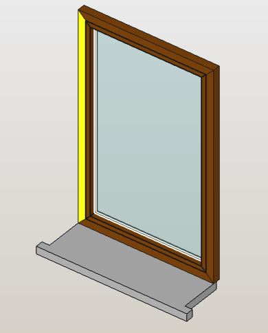
I was thinking about a frame and an opening part both 5x5 cm in section. The glass is placed in the middle and is 3+12+3+3 = 21 mm thick (just a simple box maybe?).
Then the window sill, that goes out of the wall by 5x5 cm as in the picture, that lays completely on the wall.
I’d like to have 2 getter functions like the examples below:
obj.get_default_window_(opening, frame_width=50, frame_thickness=50, etc):
	OpeningHeight = opening.OpeningHeight
	OpeningWidth = opening.OpeningWidth
	return Part.Shape()
obj.get_simple_sill(opening,  overhang=50, sill_thickness=50, etc):
	WallThickness= opening.HostThickness
	OpeningWidth = opening.OpeningWidth
	return Part.Shape()
Do you think it is feasible?
Yes, specify some dimensions to pass to the creation script, and i will put a simple test script. so we can work on some more “solid” base.
Regards
Carlo D.
Thanks! ![]()
here you have them. Dimensions in mm
get_simple_sill(opening_width=800, host_thickness=500,  sill_front_overhang=50, sill_lateral_overhang=50, sill_thickness=50):
get_default_window(opening_width=800, opening_height=1350,  frame_thickness=50, glass_thickness=20):
I was thinking: the opening object maybe can provide a boundary wire for the window generation… so we can build the frame starting from a rectangle, a circle or another random shape?
"""
 FreeCAD script - macro
 to be used with the OnePartLib part library

 copyright 2019 Carlo Dormeletti (onekk)
 carlo.dormeletti@yahoo.com

 Version:

"""

import sys
import datetime
import time
import importlib

import FreeCAD
import FreeCADGui
from FreeCAD import Rotation, Vector
import Part
import Draft
#import Mesh
#import MeshPart

# BEGIN DOC Settings
DEBUG = True
DBG_LOAD = False
DOC_NAME = "finestra"
# END DOC settings


#from math import pi cos, sin, pi, sqrt
import numpy as np


def activate_doc():
    """activate document"""
    FreeCAD.setActiveDocument(DOC_NAME)
    FreeCAD.ActiveDocument = FreeCAD.getDocument(DOC_NAME)
    FreeCADGui.ActiveDocument = FreeCADGui.getDocument(DOC_NAME)
    if DBG_LOAD is True:
        print("{0} activated".format(DOC_NAME))


def setview():
    """Rearrange View"""
    DOC.recompute()
    VIEW.viewAxometric()
    VIEW.setAxisCross(True)
    VIEW.fitAll()


def clear_doc():
    """Clear the active document deleting all the objects"""
    for obj in DOC.Objects:
        DOC.removeObject(obj.Name)

if FreeCAD.ActiveDocument is None:
    FreeCAD.newDocument(DOC_NAME)
    if DBG_LOAD is True:
        print("Document: {0} Created".format(DOC_NAME))

# test if there is an active document with a "proper" name
if FreeCAD.ActiveDocument.Name == DOC_NAME:
    if DBG_LOAD is True:
        print("DOC_NAME exist")
else:
    if DBG_LOAD is True:
        print("DOC_NAME is not active")
    # test if there is a document with a "proper" name
    try:
        FreeCAD.getDocument(DOC_NAME)
    except NameError:
        if DBG_LOAD is True:
            print("No Document: {0}".format(DOC_NAME))
        FreeCAD.newDocument(DOC_NAME)
        if DBG_LOAD is True:
            print("Document {0} Created".format(DOC_NAME))

DOC = FreeCAD.getDocument(DOC_NAME)
GUI = FreeCADGui.getDocument(DOC_NAME)
VIEW = GUI.ActiveView
if DBG_LOAD is True:
    print("DOC : {0} GUI : {1}".format(DOC, GUI))

activate_doc()

if DBG_LOAD is True:
    print(FreeCAD.ActiveDocument.Name)

clear_doc()

EPS = 0.002

VZOR = Vector(0, 0, 0)
ROT0 = Rotation(0, 0, 0)
ROTX90 = Rotation(0, 0, 90)
ROTXN90 = Rotation(0, 0, -90)
ROTY90 = Rotation(0, 90, 0)
ROTZ180 = Rotation(180, 0, 0)
#Used to shorten most Placements
PL0 = FreeCAD.Placement(VZOR, ROT0)

# DOCUMENT START HERE

fin_h = 140
fin_w = 120
fin_th = 5
cont_w = 5

def telaio():
    e_tel_w = fin_w
    e_tel_h = fin_h
    i_tel_w = fin_w - cont_w * 2
    i_tel_h = fin_h - cont_w * 2

    ep0 = (e_tel_w * -0.5, 0, 0)
    ep1 = (e_tel_w * 0.5, 0, 0)
    ep2 = (e_tel_w * 0.5, 0, e_tel_h)
    ep3 = (e_tel_w * -0.5, 0, e_tel_h)

    ip0 = (i_tel_w * -0.5, 0, cont_w)
    ip1 = (i_tel_w * 0.5, 0, cont_w)
    ip2 = (i_tel_w * 0.5, 0, cont_w + i_tel_h)
    ip3 = (i_tel_w * -0.5, 0, cont_w + i_tel_h)

    tel_b = (ep0, ep1, ip1, ip0, ep0)
    tel_bp = Part.makePolygon([Vector(*vtx) for vtx in tel_b])

    tel_r = (ep1, ep2, ip2, ip1, ep1)
    tel_rp = Part.makePolygon([Vector(*vtx) for vtx in tel_r])

    tel_t = (ep2, ep3, ip3, ip2, ep2)
    tel_tp = Part.makePolygon([Vector(*vtx) for vtx in tel_t])

    tel_l = (ep3, ep0, ip0, ip3, ep3)
    tel_lp = Part.makePolygon([Vector(*vtx) for vtx in tel_l])

    Part.show(tel_bp)
    Part.show(tel_rp)
    Part.show(tel_tp)
    Part.show(tel_lp)

telaio()

#obj = DOC.addObject("Part::Feature", "impugnatura")
#obj.Shape = impugnatura()

setview()
unfinished, but a direct creation like this, note the defining points and the frames, wait some more and i will put in place some more magic.
The window is costructed, using the bottom center as a referenfe point (origin in width é 0,5 and h = 0) so it is relatively easy to calulate the some values.
I was thinking of passing the object as a multipart object, so every part could be even sectioned with a plane, maybe even the three layer glass.
but let me work on this some more.
Regards
Carlo D.
Nice!
PS lets keep it as simple as possible, and as lightweight as possible ![]()
The window is costructed, using the bottom center as a referenfe point (origin in width é 0,5 and h = 0) so it is relatively easy to calulate the some values.
Oh ![]() , this I should have told you: the default insert point for windows is the bottom center… can we do it so?
, this I should have told you: the default insert point for windows is the bottom center… can we do it so?