I had a few ideas about wall junctions, see what you think about that and want to do that also ?
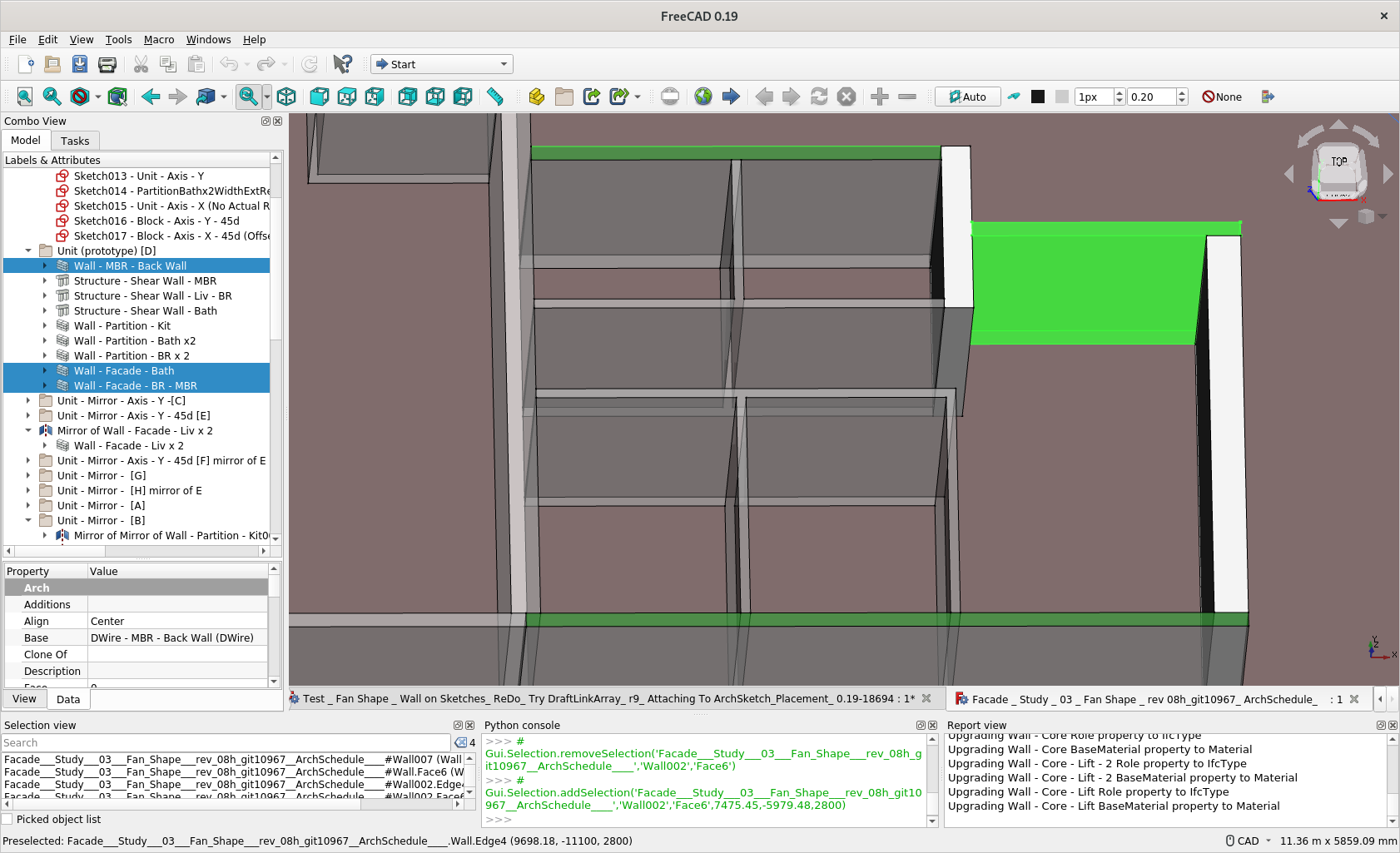
See ScreenCapture. I have a few junctions with 2 conditions with the adjacent walls - either the thinner wall is longer or shorter (and vice versa for the thicker wall). I do not need these 2 wall be merged ‘graphically’ or in terms of material - currently I needs to do this by manually extending / shortening each edges’ end in a Sketch (with constraints it is easily doable but still tedious).
I conceived there are switches like Major / Minor (maybe native English speaker suggest / correct) so they auto magically do the job. And then there can be different L-condition to choose. Now you have do the mathematics and should be easy now I think.
Well, I was thinking about the possibility to add a junction offset like @alafr did with the structure tool: so the junction is calculated and then you can move it in the axial direction of the wall. Would this solve your case?
Hey there, it’s beginning to be really cumbersome to work to this prototype inside a macro, since we have already 900 lines of code . Should I create a branch of current upstream/master (with the goal of a future integration into Arch) or maybe it’s easier to use BIM wb to extensively test the feature and later introduce it into Arch?
today update, from tomorrow i’ll be back to work, so i’ll slow down a quite a lot
Added a new property App::PropertyStringList to keep track of all the objects that target the current wall, but were not referenced back.
So now it is possible to modify them on the fly.
Also added some code to remove references when an object is deleted: imagine you reference Wall001, then you delete it, then you add a new wall and freecad names it Wall001. If references were not cleaned on object removal, you will have old walls unexpectingly joining the new one!
Well, with this implementation, the junction type will determined automatically by the function At the moment just T and L junction are supported, still do not know how to deal with X junction. Regarding X junctions, I had several ideas, because i do not want to perform boolean operations between different walls, unless it is meant to calculate for example a Shape2dView:
@geolux suggestion to split the walls seems indeed interesting, but it will result in 4 different walls (or just 3?)…
we can split just the BaseGeometry object, but keep the wall container as one…
we can just avoid any calculations and leave the 2 walls as they are (but this will result in poor visualization of the joinings)…
Any hint?
Amazing job @carlopav! Just had a look at your macro now…
Couple of comments:
I think the inner WallGeometry object is redundant. With large models, the number of document objects begins to cost a lot in terms of performance. So it’s a good practice to try to limit them as much as possible…
the main difficulty with everything in Arch, is to properly export things to IFC. That’s basically why the current code in Arch Wall is so complicated, because it tries to export “smarter” IFC objects, for ex. reconstruct the base face and the extrusion. This would actually be the right moment to think about it here too.
Otherwise, the current Arch Wall code is pretty simple. It could easily be merged into yours I would think… (better than the contrary, as yours is better organized)
Yes it is redundant for sure.
I did that because I wanted to distinguish clearly also to the user the wall and its geometry. So he is aware that he can substitute the geometry with for example a ProfileExtrusion or a piramid or a sphere, and the wall will operate the boolean operations in every case…
There is also another point (perhaps this is the main point) for having them separated. When you change the DisplayMode from FlatLines to Group, if you do not have a separate object for the shape, the wall will just disappear, instead like this we can show it transparent and the user will always know if the windows are in place with the wall or not.
Can we sacrifice a bit of performance for the sake of clarity? what do you think?
the main difficulty with everything in Arch, is to properly export things to IFC. That’s basically why the current code in Arch Wall is so complicated, because it tries to export “smarter” IFC objects, for ex. reconstruct the base face and the extrusion. This would actually be the right moment to think about it here too.
hmm seems scaring… i did not have a look at it yet… ok. i’ll have a look at the code and I’ll be back with lots of questions … EDIT: At first glance, I did not understand much… Does it have something to do with the parent classes? Is there a place or a topic where you explain the design principles of the IFC implementation?
Otherwise, the current Arch Wall code is pretty simple. It could easily be merged into yours I would think… (better than the contrary, as yours is better organized)
Wow, thanks!
I was thinking to remove all the code about the extrusion from the Wall object and make a new object named ProfileEstrusion (like the old topic about geometry and semantics with Moult, do you remember?). So maybe we can split also the IFC export part, and we can integrate them into the new object, or even treat the IFC part as a separated function…
Do not know… What do you think?
BTW, I’d like @vocx to have a look at the code too… also if it’s really rough at the moment, he is quite skilled as a reviewer
You can find it here: https://github.com/carlopav/FreeCAD/tree/Arch_new_wall_object
BUT: I tried to follow your pattern for Draft WB and to split everything in several folders, then I updated the Cmake, but when I compile it, the new modules are not added to the compiled solution… any hint?
I love to draw but I am more “mechanical systems” at the start.
I looked at ArchWB to help friends design their house, but sometimes I had some difficulties. So I got into the game of looking for ways around it. I thought my solutions could be useful for beginners and I started making tutorials.
Recently I did not go very often on the Arch-Bim forum but I discovered this morning the exciting path that you are continuing with the generation of the walls and the dynamic link of the windows with the walls.
I think this is a very interesting improvement project from the point of view of FreeCAD’s ergonomics.
Thanks also to the other participants:
You are combining also the original Wall code from the current workbench? Or only your new implementation? I’m asking because as we’ve discussed in previous threads, if you move the original classes, the older files will fail to load correctly. But if you are adding entirely new objects, these will be fine.
If the code is not being found correctly, the reason is that you are not installing the new files in the appropriate directory.
In the CMakeLists.txt file you only define new variables, but the files contained in the variables are not installed.
Hi learn you use Sketch to build wall and I watch your tutorial about wall with various thickness. Placing window on roof is amazing
We have been discussing different approach to BIM modelling here. I am advocating use of Sketch. And ‘Assembly’ / Placement of Window constrained to End / Intersection / Alignment of Wall - instead of an absolute coordinates.
At the moment just adding a new object. I do not think I will merge the old object inside the new one soon, I was thinking about doing the following:
add the new objects in separate modules (like you are doing in Draft), so the old and the new will live together and I can compare and test them separately;
split all the code in the current Wall object referring to the shape generation from a list of edges, into a new object: ProfileExtrusion. So it will be semantically free and the user will be able to use it for walls, windows, mechanical parts, etc, without having to see a brick wall in the tree view. (This second point is still a bit obscure because many things in arch are still not clear to me - I mean the design principles)
try to understand a how IFC is implemented (I probably should have started from here, but you know, i’m a newby…) and how to deal with it with the new object… and try to not break too many things…
If the code is not being found correctly, the reason is that you are not installing the new files in the appropriate directory.
In the CMakeLists.txt file you only define new variables, but the files contained in the variables are not installed.
Thanks, this CMake it’s still black magic to me…
EDIT: After one hour and a bunch of swears, the branch now compiles and run! If you want to try the tool, it’s the second wall in the Arch tools toolbar. Mind that it’s still rough
split all the code in the current Wall object referring to the shape generation from a list of edges, into a new object: ProfileExtrusion. So it will be semantically free…
Yes, sounds good.
(This second point is still a bit obscure because many things in arch are still not clear to me - I mean the design principles)
try to understand a how IFC is implemented (I probably should have started from here, but you know, i’m a newby…) and how to deal with it with the new object… and try to not break too many things…
Yes, this is the hard part, understanding the relationships between all classes. It’s the reason it has taken me a while to move everything in Draft. You can just move things but then you break everything. The trick is how to do it while keeping everything working for the user.
As for the IFC stuff. I haven’t looked at it with detail. If I remember in the past all objects were derived from the basic ArchComponent.Component class. But then Moult came and he defined the IFC.Product as the base class of everything, so that all objects are assigned an IFC class. The issue here is that the old code is still there, but maybe it’s no longer used. So, you have to follow the parent classes, and see what is called at which point.
I think if you move the most basic class, in this case, IFCProduct, then the rest is maybe easier. This is my idea with Draft as well, I need to move the most basic class, and then the rest can follow.
Thanks for the links. I had already gone through some of them with enthusiasm and I am impatient to be able to officially use the new tools you are working on (ArchSketch and @carlopav project in particular). I will study the others.
New update to take a brake from splitting Draft objects
It’s just some funny stuff before trying to tackle the IFC issue (BTW: @Yorik do you have any advice on that? what methods should I provide to be consistent with current system?)
In this way we could auto-add a window to the wall when drag on it or ask the user what he wants to do with any other object
I know that the monday morning is difficult, so let’s start with something nice!
A rough support for custom parametric windows!
The wall tool can treat every Part or Link object that have the properties: IfcType “Window”, WallVoid set to the contained volume that have to be subtracted to the wall…
At the moment the example window is a complex parametric part, but of course, you can store the parametric part as a template and downgrade it when inserting into the wall. This allows to just have 3 objects in the window: the container, the window, the wall void.
I’m quite struggling to understand some things: can you help me?
IFC compatibility: all Arch objects are represented as extrusions. In this way a wall can be seamlessly imported or exported. Is it right? So I have to be able to describe the new wall as an extrusion if we want to be able to export it. But will we then be able to reimport it again and obtain a proper wall object? Can we describe in IFC if 2 walls are joined together so we can reconstruct it properly? Or can we export a shape and save in the IFC also the wall axis and other data that we can use to reconstruct a parametric object when importing back?
what did you imagine when you wrote that the current wall can be merged into the new one?
if we split the geometry generation of the current wall into a ProfileExtrusion object, then we will have to merge just the Ifc part, is it?
what about wall block property? should that follow the wall or the ProfileExtrusion? I think the second, since it’s related to the base geometry.
If the wall container is separated from the object, it can have a BaseGeometry represented by a WallSegment, a ProfileExtrusion, or whatever else we want. And when IFC exporter ask the wall object what shape it have to export, the wall will ask it’s basegeometry for a getExtrusionData(). If not found, it will calculate the brep (or whatever needed ) and provide it to the exporter.
hope you can shed some light on my many doubts
Edit: more doubts about the WallSegment object (the wall default BaseGeometry). I do not like much the fact that the overall wall shape is visible only when display mode is set to FlatLines or Shaded etc., but not when display mode “Group” is selected.
What if it is just a container for the calculated wall shape? So the wall behaves like an assembly Part:
the wall calculates it’s shape according to the JoinFirstEndTo and JoinLastEndTo properties
if it does not have a Custom Base Geometry set by the user, it holds all the calculations of the shape, and perform the subtraction of openings and windows, and add the additions.
then it “discharge” the shape into a dumb FeaturePython object that have the sole aim of containing the calculated shape as a children of the wall… this allows to set display mode to Group and to have all the childrens always visible and fully editables directly without toggling the display mode.
in short:
Wall object
	-> Origin object
	-> WallShape (dumb object whose shape is injected by the wall object after calculations)
		the object is a placeholder for Wall object Shape at the Group level
	-> Window001 (Window)
	-> Cube (Subtraction)
Do not now if I was clear, I guess no… but I’d like to discuss a bit the project before going too far in the wrong direction
Edit within Edit: I give a quick attempt and this way seems to be far better because it also reduces code spread into more objects and we can use a super simple Part::Feature as a placeholder for Wall shape. REEDIT: Damn… the recompute chain… i did not consider that! REEEEEDIT: I think I have to go for the opposite: a super intelligent wallshape object and a dumber wall container that forwards all the properties to the wallshape… or just leave current implementation…