There are many different issues in your post, but basically:
Any IFC object can be exported as anything. It could be a simple FacetedBrep object (a solid made of flat faces), which is what we do when we’re unable to get a better way. IFC is very free-form, it supports almost all the same geometry entities as Brep/Step. But many apps rely, or work much better when objects are extrusions. Revit is always the first culprit in that regard. Certainly than 50% of the complication we have with IFC is because of Revit.
So as much as possible, we try to export things as extrusions.
Now the IFC format has another very annoying “feature”: Placements. They are complicated and some object types have very specific ways. That’s the case of extrusions for example, where the base profile must always lie in the XY plane. So we cannot just take the baseline we have in FreeCAD and apply the extrusion vector, we need to first place the base face in the XY plane, apply a transformed extrusion vector, then rotate/move everything back into position. In all Arch objects where there is a getExtrusionData method, that’s a way to try to achieve that in a way that’s compatible with IFC.
Of course we could do that in other ways, for example let objects build their geometry the easy, FreeCAD way, and have another structure somewhere else that is used only at IFC export, that would deduce extrusions from any object when needed. So the BIM objects would be free of IFC hassle and could be much, much more simple. I would have been against that in the past because it seemed not very IFC-ish, but I’m really begin to change my mind…
That’s currently what is happening at IFC import, actually. An extrusion is recreated even for FacetedBreps if it’s possible.
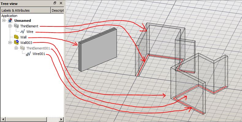
IFC objects can also have several representations. This is often used in walls, where there is one solid representation, the extruded solid, and one axis representation, that contains the wall baseline. I heard some apps use that to recreate the complete parametric wall with its baseline, but I never saw it really working. Also because there is no way to “bind” the axis with the base profile of the extrusion, so it’s flaky to know how to use the axis.
One thing I’m really not liking is to have several intermediary objects in each wall. If you think of a 1Gb IFC file, which is not uncommon at all, there can be hundreds of walls. It is already hard to bear by FreeCAD as it is now. If each wall is made of 2 or 3 objects, we’ll end up with hundreds of additional objects, which will clog things even more and become a serious limitation to use FreeCAD for BIM for many people. I think we need to keep things with as few document objects as possible.
Internally of course, nothing prevents from having different components, modules, derived classes, anything you see fit. But while these things are fine for PartDesign-like workflows, we really have to think “economically” with BIM.