Hmm that’s a bright idea… One toolbar button, but inside the tool, “tabs” or “sub-buttons” somehow. This could apply for all those tools that have multiple submodes, like structures, windws/doors, rebars…
What about “joinery”?
I’m moving this thread to the BIM section, it’s more logical…
Hello, just wandering around with my mind and thinking about 2d representation in the BIM Workbench and about the section tool, that is already really powerful, but could be the key to produce ready to print 2d documented views.
I was thinking… if the section tools could contain also 2d elements, like detail lines and dimension that only have to be shown when we are looking at the model from that section plane. Also the section could be setup when creating the corresponding level. Also, when activated (double click on his main group) change the view (like the sketcher) and hide the other sections. It could contain the scale for dimensions and other useful things.. ok, and i came up with the screenshot below. Do you think it could be useful?

I have exactly the same plan as yours ![]() BTW, arch sections can already have 2D objects. I also plan to extend the BuildingPart to have an implicit, “embedded” section plane. So you would basically have three objects to work with, to deal with views:
BTW, arch sections can already have 2D objects. I also plan to extend the BuildingPart to have an implicit, “embedded” section plane. So you would basically have three objects to work with, to deal with views:
- Section planes: do not contain objects, define a 3D view (not yet), define a 2D view
- Building parts: contain objects, define a 3D view, define a 2D view (not yet)
- WP Proxies:do not contain objects, define a 3D view, do not define a 2D view
I knew u were the man. ![]()
Great. I didn’t understand the building part were same as levels.
It would be perfect if the initial setup could build also default views associated to levels. Then the user can add others or duplicate them.
“… to extend the BuildingPart to have an implicit, “embedded” section plane…”
That would be very productive ![]()
They are. This is to be flexible. Lots of building types may not have levels but other geometric boarders than levels to splitt them into pieces, thus the building part was indroduced.
yes, the “basic” use of Building Parts is to make levels (or storeys, floors, whatever). But being forced to divide your building into levels always annoyed me. What of an elevator shaft, for example? Or a glass curtain façade? Of course you can “fake” making a separate level only for it. But that’s not correct semantically.
So the Building Part is basically a grouping of BIM objects. By setting its IFC role to “Building” or “Building Storey”, you turn it into a building or a level, simple as that.
At the moment, they behave like a group, that is, an object can only be inside one BuildingPart. But we could also easily remove that restriction, I’m actually not sure if it’s a good thing or not…
But there is another important feature too, BuildingParts have a Shape property, that is a compound of all its children. So they are basically a hybrid between a group and a part object. So they can be cloned, referenced in another file, etc. The idea is that you can also use BuildingParts to make repeatable components, such as a bathroom stall. If you set their IFC role to Element Assembly, they are exported as such to IFC, and reimportable as is.
But the main workflow I see is that you would use a BuildingPart as a level, work inside it (place it correctly, look at it from the angle you wish, right-click it in the tree view → Write camera position, set its “Restore view” to True, and when you activate it, you’ll find yourself all set, in that view. I’m planning to add an implicit section plane to it too (you can specify the height/offset), and the possibility to hide all other objects while you’re working in (same as WPProxies). And maybe the possibility to cut the view, like the section plane does, but I’m not sure if it will still be practical to work with, that needs testing.
They are. This is to be flexible. Lots of building types may not have levels but other geometric boarders than levels to splitt them into pieces, thus the building part was indroduced.
I agree, I think the concept of levels is more semantically related to representation (since we experience buildings floor by floor, and so they perfectly identify plan views for example) than to group building components (that have more sense to follow other rules, the ones of construction for example, as workers will first build storeys and at the end add a curtain facade).
So the Building Part is basically a grouping of BIM objects. By setting its IFC role to “Building” or “Building Storey”, you turn it into a building or a level, simple as that.
Perfect to me.
At the moment, they behave like a group, that is, an object can only be inside one BuildingPart. But we could also easily remove that restriction, I’m actually not sure if it’s a good thing or not…
I think this is again correct. it forces a bit to be tidy, but that’s not bad. Again it would be good to control in views which part has to be shown or eventually which components in the part.
But there is another important feature too, BuildingParts have a Shape property, that is a compound of all its children. So they are basically a hybrid between a group and a part object. So they can be cloned, referenced in another file, etc. The idea is that you can also use BuildingParts to make repeatable components, such as a bathroom stall. If you set their IFC role to Element Assembly, they are exported as such to IFC, and reimportable as is.
But the main workflow I see is that you would use a BuildingPart as a level, work inside it (place it correctly, look at it from the angle you wish, right-click it in the tree view → Write camera position, set its “Restore view” to True, and when you activate it, you’ll find yourself all set, in that view. I’m planning to add an implicit section plane to it too (you can specify the height/offset), and the possibility to hide all other objects while you’re working in (same as WPProxies). And maybe the possibility to cut the view, like the section plane does, but I’m not sure if it will still be practical to work with, that needs testing.
That sounds very good.
What misleaded me about building parts and levels is that the icon in the tree was slightly different ![]()
Yes and I’m still not totally happy with this icon… ![]()
I could think about it maybe…
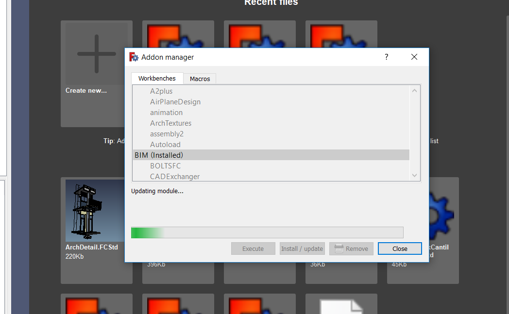
Hi. Since some days ago the Addon Manager keeps updating the BIM module without stopping.
OS: Windows 10
Word size of OS: 64-bit
Word size of FreeCAD: 64-bit
Version: 0.18.15656 (Git)
Build type: Release
Branch: master
Hash: a60b6957db228c42a00a1e002a415cbb8309d3c8
Python version: 2.7.14
Qt version: 4.8.7
Coin version: 4.0.0a
OCC version: 7.2.0
Locale: English/Australia (en_AU)
Fixed. I just manually deleted all BIM folders in AppData and reinstalled them with Addon Manager. Now it updates normally.
No problem for me… Thinking about your other bug in another thread, is it possible that you have the BIM WB installed twice?
EDIT I had missed your reply. Great!
Hi, I am starting to use this tool. thanks for the work !!
I would like to ask a question, sorry if it is duplicated, I could not find it on the site.
Every time I start the BIM WB I got the error message:
"Workbench failure: “module” object has no attribute “addDocumentObserver”
I also installed it on Mac and got the same error.
Thanks.
Cheers,
Enrique
OS: Windows 10
Word size of OS: 64-bit
Word size of FreeCAD: 64-bit
Version: 0.17.13541 (Git)
Build type: Release
Branch: releases/FreeCAD-0-17
Hash: 9948ee4f1570df9216862a79705afb367b2c6ffb
Python version: 2.7.14
Qt version: 4.8.7
Coin version: 4.0.0a
OCC version: 7.2.0
Locale: English/UnitedKingdom (en_GB)
Indeed some latest code is only working on 0.18… I just added a switch that disable that functionality on 0.17. Try updating the BIM workbench, it should work now
Did work !!
Thanks
Have a nice day.
Hi to all
I kindly ask if I’m doing a mistake when I draw a steel structure using the Arch Structure tool or there is a bug in Freecad. If I use steel profiles for columns (IPE or any kind of those which are available in the library) it correctly works, when I draw a beam, something strange happens: with rectangular sections the beam is correctly modelled from a first point to the second while a steel profile beam appears as a column (vertical and not horizontal) placed in the starting point. I’ve discovered that in this tutorial the steel beam was differently modelled; is it the only way using the Arch Structure Tool or have I made something wrong?
Thanking in advance for your answer
Happy Easter to everyone
I just stumbled on this problem too, drawing beams seems a bit broken… Will fix that ASAP!