Another approach to assembly solver (A2plus)

So deep integration with PG would be great! :slight_smile: Hope to see it one day.

However for experimenting with new database-centered workflows we need very modest level of integration: just ability to somehow keep and retrieve FCStd file contents in database records with some custom fields.

  1. It seems that sqlite is already used in the FC
  2. one through problem in the FC is details associations: what dan-miel pointed: replacement of the part in one file - destroys associations.

for that last - very needed would be to have a table (left-right) of present associations available to replace them manually. And then the idea of backtracking would have sense.

Unfortunately I did not find how to work with sqlite in FreeCAD :frowning:

Now I am thinking about generating virtual disk or filesystem.

FreeCAD and any other tool can browse “folders”, read and save “files” which are really processed with some custom python code which retrieves them from database. Thus I can draw two cubes with FreeCAD, save it to ~/PLM/FreeCAD/1.FCStd, then open e.g. with Excel folder ~/PLM/Excel/1/list_of_cubes.xls, delete there one of them, and then open ~/PLM/FreeCAD/1.FCStd with FreeCAD - and see there no second cube. And, of course, I can undo or extract older version through custom PLM interface - into specific folder.

If A2plus FreeCAD assembly A.FCStd file have link to my FreeCAD file B.FCStd (as sub-part), when I try open one of these files it can be generated already with all tables of dependencies, hyperlinks (pointing inside of virtual filesystem and being really PLM commands, and other arbitrary objects). Thus FreeCAD only works with files, but links - direct, lateral or reverse - are stored and managed in independent database. And I can work with cross-file networks of these links: I can take any diagram editor (supported by my code under this virtual FS), inspect/add/delete/repoint links - and on file save this is automatically reflected in my assembly structure.

Here part paths for A2plus (or, due to universality, for any kind of Assembly workbench file) are generated on file loading and can not be broken occasionally due to database supervision.

Screenshot_2020-09-25_14-23-47.png
So we can end up with ultimately simple in installation (and integration with all kinds of software tools) PLM: just running script mounting and serving virtual filespace. Could anybody suggest an appropriate python library for it? (I am not so good in other languages)

OS: Linux Mint 20 (XFCE/xfce)
Word size of OS: 64-bit
Word size of FreeCAD: 64-bit
Version: 0.19.22670 (Git) AppImage
Build type: Release
Branch: master
Hash: 12155f4aab09047c5697db0c1b3cf93b02edda03
Python version: 3.8.6
Qt version: 5.12.9
Coin version: 4.0.0
OCC version: 7.4.0
Locale: English/United Kingdom (en_GB)


It’s a long time since I tried A2+ and I suspect there will have been improvements so I am keen to try again. I have recently tried Assembly4 but that does not seem terribly intuitive to me. I have also tried Assembly3 which is more intuitive than Assembly4 but still not as intuitive as A2+.

When I last tried A2+, there was a the problem of assemblies breaking if a component part was modified after assembly (think that’s the topological naming problem). Can anyone tell me if that is still a problem to be aware of?

Looking on the A2+ wiki page (here) I am interested to try out the scripting for animation. I find however two problems:

  1. Animation.FCMacro", line 3, in
    import A2plus.a2p_solversystem as a2p_solver
    <class ‘ModuleNotFoundError’>: No module named ‘A2plus’
    I do have A2plus installed though. What’s the problem here?

  2. If I use the other macro which uses a Qt interface, my computer simply locks, completely and irretrievably requiring a hard reboot. It could be linked to problem 1 above and if I solve that, the Qt interface one might work.

Any ideas?

There seems to be a little error. Please use:

import FreeCAD.A2plus.a2p_solversystem as a2p_solver


I did not test this yet.
.

Yes. This is still a huge problem for complete FC.
A2plus has a build-in mechanism to reduce the problems caused by reordered vertexes,edges faces. You should activate the A2p preference “use experimental topological naming”

Next to screenshots are showing, what is happening without using that option. A simple basepart has been connected via 3 plane coincident constraints. Everything seems to be fine. Only applying one champfer to the basepart leads to wrong assembly result. See here:
no-toponaming-1.png
no-toponaming-2.png
.
After that, i activated the preference “use experimental topological naming” and started a complete new assembly. Using this option leads to geometric informations in the mux-info field of an imported part. This infos are used to recover reordered geometric elements.
See the new assembly here:
.
with-toponaming-1.png
.
Now i could do horrible things to the original parts without blowing up the assembly:
.
with-topnaming-2.png
.
I attach the files. Via Partdesign WB you can iterate back by setting the tip of the parts, to get earlier states of their features. After saving and updating the assembly you can see that it keeps stable.

But there are still many ways to get problems with the topological naming issue. Add new lines to a sketch. This is enough, if the sketch is used for a pad which is referenced by a constraint.

P.S. For testing the files you have to activate the preference “use experimental topological naming”. Otherwise nothing will work.
files.zip (109 KB)

Thank you, that works with that correction. It’s not the same problem in the other macro but at least one of them is working :sunglasses:

Wow, that’s brilliant! :astonished:

Can anyone help me understand how to lock the rotation of two parts so that if one rotates, the other rotates?
I’ve tried both the circularEdge constraint and the axisCoincident constraint with the “lock rotation” set to true however if I then rotate one part, the other does not rotate when I press solve. What am I missing? I’ve attached a really simple example file.
Screenshot1.png
A2P V0.4.47e
OS: Linux Mint 20 (XFCE/xfce)
Word size of OS: 64-bit
Word size of FreeCAD: 64-bit
Version: 0.19.22670 (Git) AppImage
Build type: Release
Branch: master
Hash: 12155f4aab09047c5697db0c1b3cf93b02edda03
Python version: 3.8.6
Qt version: 5.12.9
Coin version: 4.0.0
OCC version: 7.4.0
Locale: English/United Kingdom (en_GB)
a2p_test_rotation.FCStd (7.8 KB)

Hi,

lock rotation has never been implemented, it’s an old property used in previous assembly2.
You can try constraining objs to an external sketch, it is a very powerful feature of a2plus

Valerio
a2p_test_rotation.FCStd (10.5 KB)
schetch sample.FCStd (3.7 KB)

Hi

I am trying to make a McPherson strut using A2+, but encountered wired problem with moving parts.
Error “animation problem detected” appears in positions where whole model should behave quite stable (nothing “strained”, all angles looks good etc.)

Model contain “armRF” constrained to fixed rotation axis (FixCylinder) and spherical to “KnuckleRF-asm” on the other side.
Knuckle (green part - in fact knuckle and bottom of shock absorber in one part) is constrained spherical to “SteeringRod” and axially coincident to “ShockTopRF”.
SteeringRod (yellow on model) is spherically connected on both ends between fixed mounting point (FixSphere_001) and knuckle.
“ShockTopRE” (top grey part of shock absorber) is spherically connected to fixed |FixSphere_002) on top.

All files included - A2+ assembly is in file frontAsm.FCStd, in two other FCStd are models used in assembly.
Also I attached few pictures of assembly and tree.

And in general model works, can be solved resulting proper alignment of all parts with message:

===== Start Solving System ====== 
20:20:35  
20:20:35  convergency-conter: 151
20:20:35  Calculation stopped, no convergency anymore!
20:20:35  TARGET   POS-ACCURACY :0.0001
20:20:35  REACHED  POS-ACCURACY :0.00013470727165820507
20:20:35  TARGET  SPIN-ACCURACY :0.0001
20:20:35  REACHED SPIN-ACCURACY :9.659346157805867e-06
20:20:35  SA SPIN-ACCURACY      :0.00021294593556323688
20:20:35  ===== System solved using partial + recursive unfixing =====

But when trying to animate it, in positions where lower arm is closer to horizontal positions, everything starts to broke apart, with an message “animation problem detected”, that happen every time when reaching similar position of model. When “animation problem detected” appears, I can still click on “solve constrains” and it works, but still can move model in that direction.

But is works quite well in position where lower arm is nearly vertical.
Positions where problem occurs not seem to be complicated - nothing is strained, all angles looks sane, so have no idea why.

Any advice how to handle such issue?
Is this possible to run solver in more verbose mode, to be able to understand/debug such problem by myself?

Thanks :slight_smile:
tree.jpg
A2plus V0.4.47e
OS: Ubuntu 20.04.1 LTS (ubuntu:GNOME/ubuntu)
Word size of OS: 64-bit
Word size of FreeCAD: 64-bit
Version: 0.19.23058 (Git)
Build type: Release
Branch: master
Hash: 6e60870ebcb2df018adb7a1281c00dde87750f11
Python version: 3.8.6
Qt version: 5.12.5
Coin version: 4.0.0
OCC version: 7.4.0
Locale: English/United States (en_US)
frontAsm.FCStd (57.4 KB)
armRF-simple.FCStd (220 KB)
armRF.FCStd (190 KB)
mcpherson.jpg

Hi,
nice model ! I can reproduce the problem and i guess, this is some instability of the axisCoincident constraint. I will have a look at the code, whether there is a bug or something else what can be improved.

As a temporary solution i inserted an additional pointOnLine constraint, see the red parts in the screenshot.
.
New-PointOnLine-Constraint.png
.
Compared to other numeric solvers the one of A2+ is not sensitive to redundant constraints and sometimes an additional constraint can stabilize computations. With adding the pointOnLine constraint at least i could extend the range where the simulation is working properly.

Nevertheless something is wrong with the solver here. But i need time to investigate this. Please find the modified files attached.
.

Unfortunately there is no more verbose mode. Debugging of such issues is very complex and is usually done with a lot of printouts from the code.
a2p-McPherson-modified.zip (482 KB)

Ok, got it.
Thank you for help.

I also noticed that solver works more stable then in animate mode, when I just change constraint parameter and click solve.

So in my example I changed from axisCoincident constraint between shock absorber top and bottom (kunckle) to circularEgde between edges with offset.
And with simple macro I can animate this with way more rare instabilities (mostly because I added few more constraints now for axle and constant velocity joints)

for x in range(10, 150, 10):
	FreeCAD.getDocument('frontAsm').getObject('circularEdge_005_mirror').offset = str(x)+' mm'
	Gui.runCommand('a2p_SolverCommand',0)
	Gui.updateGui()

for x in range(140, 10, -10):
	FreeCAD.getDocument('frontAsm').getObject('circularEdge_005_mirror').offset = str(x)+' mm'
	Gui.runCommand('a2p_SolverCommand',0)
	Gui.updateGui()

Did your assembly fail during script execution ?
I added one circularEdge constraint, adapted it’s name in the script and it is working on my side.

In model that I sent before it works without fails.
But now I have a bit complicated model, with added few more constraints and now it sometimes fail, even when configured from script.

Possibly too much constraints at the time right now

If your new assembly isn’t top secret, please post it. I will then have a look. There are still other optimizations possible (Adjustments to the solver).

In my model I fixed ShockBtmRF_001 to KuckleRF_001 with two circularEdges - it is not necessary (in previous model two parts was merged), but I like to use it that way to simulate wheel alignment setting using eccentric fasteners between that two parts.
But it not caused serious convergency problems.
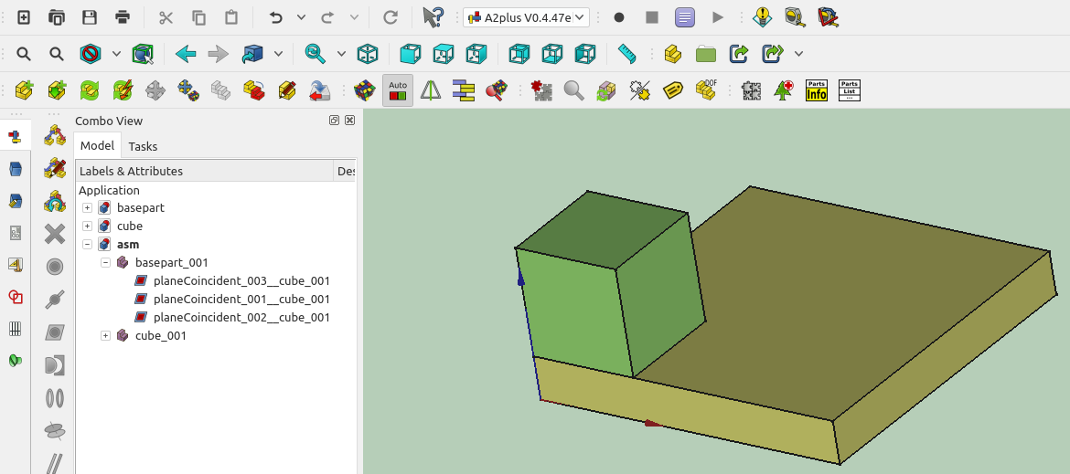
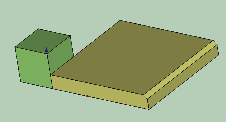
When I added green axles, the problems start to rise and right now, just when you load model in it default position solver is unable to solve it.
In some orientations it still works, but really hard.

I also took a look into source of your solver.
I like how it is written - nice clean code, that I can read and understood even with nearly lack of Python knowledge.
But maybe it is good time for me to finally learn Python ? :wink: (as a C/C++ programmer I can’t get used to Python indentations)

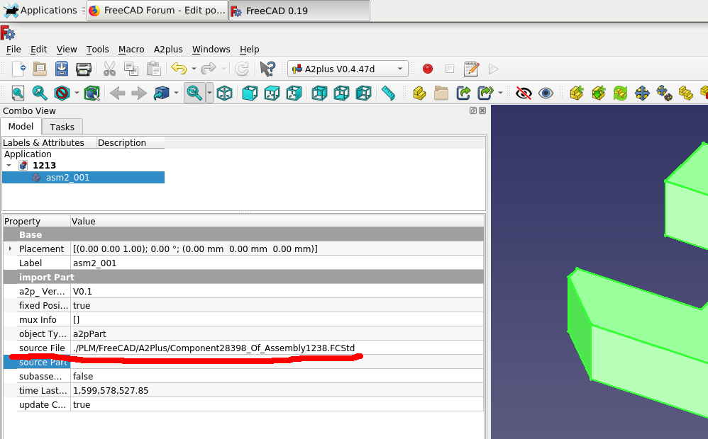
I was able to do step-by-step simulation by changing solverControlData to do more smaller steps of pos/spinAccuracy, and not requiring accuracy below 0.05, but I looked around whole your code.
I spent only 2h looking into it. so just got some basics of your concept, maybe you would like to use some of my experience with similar problem, that I resolved with similar idea as your.
Main difference was that I was not applying ‘move’ to rigids to lower an error, but I was applying just a force like a spring - when error was bigger, there was bigger force applied for both rigids to bring then closer to proper position.

Each rigid body had own mass and moment of inertia (I think for such FreeCAD solver it could even be a random - I love randomness in numeric simulations) - so applied force changes a speed of rigid body and rotation around body mass center (when applied not directly into mass center it generates torque).

It would end with endless vibrations, so each constrain also applying a dump force. Each constrain measuring it own stretching/squeezing (could be also rotating etc) speed measured just like: (last_frame_length-this_frame_length)/frame_time and applying dumping force proportional to that speed, but with opposite direction.

To stabilize calculations I added in similar way as you, some ‘play’ distance that was permitted error for each constrain.

Finally every rigid calculates resultant force and torque that changes speed and rotation of this rigid.
Then each timeframe results in changing position and rotation of each rigid.

With ~100 simple constrains, and few thousands steps per frame I was able to solve it still with 60fps (and it was 10 years ago on one thread) - for sure my constrains was simpler, and permitted errors was higher.

I think it could be good idea to use more physical-like simulation - changing speed and rotation between each convergency step should give result even faster.
suspension.tar.gz (361 KB)

Hi @topyra,
thank you very much for your detailed feedback. I see, you have a lot of experience with simulations.

Very good idea. A good IDE is managing the indentations. (I use Eclipse with the PyDev plugin)

When i remember correctly the start of this project, i tried something similar. Perhaps i have made to many mistakes, so i did not have success.


Using Python instead of C/C++ is much slower, because Python is an interpreter language. You can calculate factor 50-100 slower.

Trying this again is a fine exercise for rainy weekends.

Thank you for your files. I will try to analyse what the problem is. In past, such instabilities often dealed with calculating (moving) refpoints. An example is the nearest point between to axes. With each calculation step it can jump from one place to a far away another one.

P.S: or it was just a programming bug. :smiley:

Greetings,

So far I figured out that problem is in two circularEdge constrains that connects armRF_ShockBtmRF_001 and armRF_KnuckleRF_001

i.e. for armRF_KnuckleRF_001 one of constrains returns moveVector.x = ~ 0.08020…, but second returns ~ -0.08173
And despite that both constrains have significant error ~0.08 (that is biggest error here) moveVectorSum is about zero and step do not going to solve.

From model side it may be fixed just by remove this two constrains and merge this two parts.

But from solver point of view it looks like the issue is with adding move vectors that in this case subtracts two moves in opposite direction.
In physics when object is pushed in two opposite directions it do not move, but when this forces are applied in different origins (and that is what we have here) the object starts to rotate.

In time based simulation with applied force, the rotation coming from each force is around mass center, around axis that direction is (AFAIR) dot product of force direction and origin (in LCS where mass center is in 0,0,0), divided by moment of inertia of rigid.
Sum of rotation vectors from all the forces applied to rigid is the resulting rotation.

You are working on ‘moves’, but guess rotation should be calculated in similar way - I need to think for a while on it.
I found that you already calculate it in depRefPoints_Spin and depMoveVectors_Spin, but this rotation is way too slow, or there is something else not right here - I’ll try to debug it out.

BTW - do you know how to draw, from Python level, a 3D arrow of given origin and direction?
It would greatly improve my debug capabilities to draw some arrows representing all the intermediate vectors that are used to calculate each step of solving.

I have made a help request in the scripting section.

Hi @kbwbe, care to post a link to said thread?

Edit: found it
https://forum.freecadweb.org/viewtopic.php?f=22&t=52807&p=453592#p453592