kbwbe:
Thanks for adding the commands that you have and for the amount of time you have spent looking at the efforts I’ve made to make a constraint fixer program. One reason I’m pushing for this is, at least the way I see it, if A2plus gets configurations the conflict problems are many because when moving from one configuration to another you move the constraints also, which can make a mess.
The “a2p_solversystem.solveConstraints” command is great. It retrieves the blasted constraint that causes the problem. ‘PS’ not all of my conflicts are caused by the last one and this command finds them.
Adding the ability to add some mates to a list and run just the list instead of all of them is great also. I hate to sound like a complainer but here goes anyway.
I like the ability to turn off the error messages. I noticed the error messages for the parts that don’t move are now popping up one at a time instead of as a list like they did before. Would you put them back into a list and perhaps give us a chance to retrieve the list so I can handle them in a different way? ( Do you like the way I said “we” and “us”?)
The matelist for solving constraints: When I’m solving many lists there is a lot of print flowing into the report window and it can be hard to find information that I print. Can we have an option to turn it off.
When the error message pops up: Many times I’m zoomed in or out and the errors are outside my screen or small or hidden. The screen is frozen because the popup locks it so I cannot find the parts. Could the form be changed so we could look around?
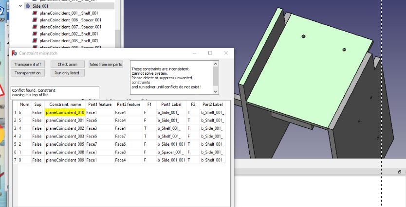
Lastly I’m attaching my latest poorly written attempt and a picture. The new commands saved time, coding and I did not need to change the solver file to get the conflict. I can leave the form open and work. When the cursor enters a cell in the table the information in cell highlights. Column 2 highlights both legs of the constraint, columns 3 ,4 highlights one leg at a time. Column 1 shows if the constraint is suppressed, 5 and 7 shows if the part is fixed. When a check is done and a conflict is found the program reads which two parts the constraint legs are attached to then finds the other constraints that are attached to the same parts and send the constraints to the table to be viewed. You can also manually select parts and pressing the middle top button finds the constraints attached to the selected part/s and shows these.
There are problems yet, several crashes, that I haven’t fixed. I also plan to get columns 1, 5 and 7 to toggle True/false so that constraints can be suppressed or parts fix for testing without having to open the property window but today I’m just. Just not smart enough.
Dan
PS: While looping through FreeCAD obj files sorting by ‘ConstraintInfo’ some mirror files slipped by. My machine? I could not find the cause.
kbwbe
I’m still trying to ease the pain when a part is changed and the mates blow up. I hope you have a moment to let me know how much trouble I‘m heading into by changing the mating parts in your constraints. I have 3 projects that I hope works together at some point.
You’ve seen the first that shakes the pile of parts to find lose ones.
The second that I’m just starting to think about is how to examine the differences before and after changes to try and find the entities that hasn’t changed to reconnect the mating parts. The attached picture shows a simple part that ca n be done by a human but they can get complicated quickly.
The third is to change the information in the constraint without destroying and creating a new constraint. I sometimes wonder if it will cause a stability problem further down the road. So far I have changed the information in constraint with but not the mirror. I know that you are busy but if you know problems that I will run into and could them put down in a few word them I would appreciate it.
Thanks
Dan Miel.
I know that these are not a fix but hopefully they will help.
Here is a 30 second video of changing constraint links. Every time I click on a surface the link’s name is changed to the surface I clicked.[url]https://youtu.be/obgvMZYpVE4[/url
In V0.4.47, I have my units set to imperial and am trying to enter an offset in a coincident constraint. It defaults to mm, but it won’t let me type “in” to define the units. How do I change units of offsets?
When doing a check I get tons of messages:
It would be nice to get all those messages in a list and / or having the option to abort the check.
The root problem is actually rotating some objects were not rotated properly due to floating point issues it seems. After some chained up assembly the entire thing does not really match anymore due to those issues.
So I’m trying to delete some rules and it ends up in a mess of course (until I have things somewhat balanced again - “somewhat” because the assembly is not fully accurate)
Does anyone know how to get around that?
Welcome to FreeCAD Mrx. A2plus does have it’s problems. I have tried to overcome some of them with third party programs with some of my ideas working better than others. problem 1: The message of “highlighted parts were not moved” is likely because you tried constraining two parts that are not constrained to the base fixed part. Problem 2: inaccuracies’: I’m not sure what is not accurate in your screen shots. I do see that the one dimension is 153,1141 and the other is 133,1141. but it doesn’t seem like it would be 20mm off. I wrote a program that reports the errors as a list and I had to set the precision to 5 places but that is still far from 20.
Dan
I usually remove the constraints and update the objects. After that I’ll re-apply the constraints (because just updating the objects doesn’t seem to work properly - or in some cases I’m modifying the objects too much).
The problem is if you have a bigger design, there are too many of those popups.
Do you know about the freecad code? I think some kind of labelling the faces could help to fix the updating issues.
Unzip the file. Copy the directory to you “mod” directory and restart FreeCAD. Right click in the icon rows to add the new buttons to your customized dash.
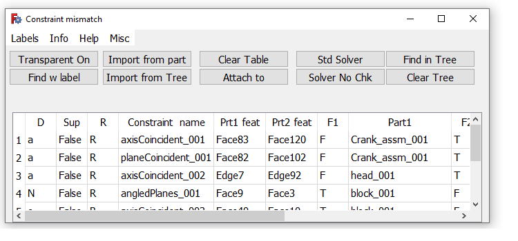
You said the word “update”, evil word. I’m attaching a work bench which consist of 4 programs. I’ve been told that the programs are too complicated and they are but I use every function so please bear with me. First the features of the part is numbered and when a part is changed, say a hole is added, the feature changes it name but the constraint doesn’t change the name of that link so you end up with broken links. The update program tries to find the same feature or something close and reattaches the link. So next time you modify a file leave the constraints attached and update using the orange update button. To do this select the part that you modified and select update. Yes it only updates one part at a time. but I only modify one part at a time. It will also run the checker program with the green arrow automatically. If the update program could not find a feature a popup will state there are missing constraints and do you want to view them? Click yes and a dialog with a table will appear and the missing links will be yellow. This is the viewer. Clicking the constraint name column will highlight the two mating surfaces, if there were two surfaces but there is only one. Figure out where the missing surface goes and “click in the yellow cell” then click ‘attach to’ and select the feature you want to attach it to. And it should attach.
A long explanation but it only takes seconds to fix when it works. Try it a few times. To view all of the constraints from a part Click the lantern to open the viewer, select a part then click “Import from Part”. All of the constraints will be loaded, or select some in the tree and click “Import from tree”. Turn the assembly transparent to view the constraints. Also if you cannot find a feature then press the “find with label” button. Press it again to remove the label.
I absolutely understand your concerns about updating, I think this should be solved on a higher level allowing to attach the labels to an object (eg. explicitly adding a “Front” label to a Face)
I’m also refining the objects from time to time so it could be that some “selected” faces completely disappear from time to time. So why not attaching labelling support to the object structure directly.
I think you’re working on the other end of FreeCAD.
I hope I did not misunderstood your post when you wrote about labels, did you mean faces?
Overall I’m quite happy with a2plus, just sometimes I run into tricky problems with it (which I was able to solve luckily).
Update 1:
I only downloaded it and had a look at the python code, seems like it’s not so difficult to get into it, so I’ll try to study the plugin within the next days.
One more thing, my workflow is that I assemble parts using a2plus but also design new parts based on the results of that assembly (eg. connectors to join 2 parts).
So I’m mixing a2plus objects and regular partdesign objects (the ones with the blue bricks).
As far as I’ve learned it’s not possible to mix partdesign objects with a2plus objects, however it would still be valuable to be able to align surfaces of partdesign objects with a2plus objects (even without creating rules).
Currently I look at the coordinates and move such items manually.
Update 2:
it is possible to define rules for “Partdesign Objects” however they’re placed outside of the object and cause weird issues (I remember I had those issues also when I started with a2plus). At that stage seems like I’ve nailed down all my issues.
I thought that any object can be assembled in A2+ Part design or not. All I use are part design.
A couple rules for the updater.
1 If all that you modify in your part is dimensions then use the standard updater. If you add or delete faces, add or delete holes, then use the one I sent you.
2 It might not like copied parts. I don’t remember what it does I just remember that I added the arrays last.
Dan
What do you mean that you are mixing a2plus with partdesign objects? And that the part design are outside of the object and you move them manually? Everything I work with is inside the assembly file. If you have things ‘outside’ of the assembly file the programs may not work as intended. If you would, please send me an assembly and I would like to see what results I get with my programs.
If you are referring to the last line of the message I mean that an actual label will appear at the location.
Is the code working? I am recovering from some surgery I had last week so I am home all day and have some time to look at it.
Dan
Here is a demo of updating the part. At the end of the video I show that all of the constraints are still in the assembly.
Dan https://youtu.be/JQC-P8fVJOU
I propose to print this message after all the other checks, and not during the check.
I have 126 parts in my design at the moment and many rules it takes quite some time to go through the checks. (the conflictfinder takes > 30 Minutes)
msg = ‘’’
The highlighted parts were not moved. They are
not constrained (also over constraint chains)
to a fixed part!
‘’’
QtGui.QMessageBox.information(
QtGui.QApplication.activeWindow(),
“Could not move some parts”,
msg
)
the issues should be collected and displayed at the end, this is just stopping the check and waiting for user input.
I’m not into all that, is there a way to update the script without having to restart FreeCAD?
Copy/paste the A2plusupdater file into the mod/A2plusmore folder. The conflictfinder will not run. After the updater runs if there are missing features the viewer will open.
I see that you remarked out Lines 518 - 522. I would need to add code to the solver file which would get wiped out each time a2plus was updated so I try to leave those files alone. That error is created because the two parts are not constrained to a fixed part. I’m not even sure if that is really an error, I think a note at the end would suffice. A lot of times when I get that error I just fix one of the parts.
It would be nice to have this solved at a higher level but I find it to much of a pain to remove all the constraints and redo them so I’m tackling it at this lower level.
Suppose, that multi-select - align. might be possible to solve by adding the CTRL to separate source from target.
Like select multiple sources - press CTRL - select target → constrain.
And maybe the more required option would be to disable popup: set multiple constraints without having the "Set / solve " constraint popup.
QUESTION:
In the imported parts there is a property Fixed Position = true/false
In the properties editor it is possible to add new property (or via python scripting)
How to add property to a sketch, so that A2P solver would consider the position of sketch - fixed??
Would be efficient in A2P to have a constrain-tool-button [AddFixedPositionPropertyToObject]
And also a very needed tool is: Apply <fixedPosition = true> to constrain-positioned parts.
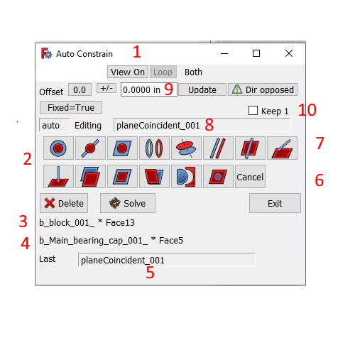
For muti select it is #10 in the PDF file or “Keep 1”
There is no pop up in this workbench. Select two surfaces you have your constraint. If you want a different constraint select it before you select the second feature.
Everything your asking for is write your own or (third party). My write my own is below and Yes there are bugs. I have the program on this machine but I haven’t tried it on my other machine. Let me know if it works or not.
Question is: how to import a detail with a2plusmore into asm?
What is the general work-flow with this workbench?
And else, could you, please, provide a dependency graph of the project files?
After trying o use:
convenient.
but guidelines still must depend on an imported part (no option to set fixedPosition = true)
Need an option to start solving based on guidelines located in the assembly file.
And also, seems that at this moment the best would be a combination of tools/toolbars from A2P and A2P-more.
And to get it working I had to copy some files from A2P folder.
In the attached files - there is a detail->guidelines dependency assembly made with A2P 0.4.47d
A2P-more did not accept guidelines.
And what I’m willing to have: guidelines → detail dependency det1.FCStd (3.69 KB) det2.FCStd (3.69 KB) Asm2PM2.FCStd (9.99 KB)