It depends, design intent.
I feel that this qualifies as being a top down design. Sketch in document A was “linked” with this latest feature of A2plus, from an external document. I attached a new sketch on it, added new circle and used the link as a reference. Could have just Part Extruded the link directly. Increasing the radius of the sketch in document A increases the radius of the shape in document B (after document A save and A2+ recompute operation). Now i guess you already got a few ideas, on where exactly you could attach some coordinate systems and use Assembly 4 as a complementary option. ![]()
Do you feel App::Link will someday support such Sketcher geometry sharing cross-documents? Or is that out of scope, as far the App::Link is concerned?
Hi @ppemawm,
first, i am very impressed about all the complex models you have already done with FreeCAD. Very impressive.
My idea for the new feature within A2plus is quite the opposite. My idea goes that direction:
- I create a master document with multiple sketches and if needed, spreadsheets, for the job to be done.
- Perhaps one sketch each for the outer dimensions, axis distances, guiding rails, fixing points, section sketches. Even on different working planes.
-
If the master document is looking ok, there is time to create first parts.
For that, a new document is created and at first step all the relevant sketches from the masterdoc for that part(s) are imported for reference purposes.
It is even possible to create only one part according to the imported sketches or even more parts for e.g. a subassembly, which can
be edited in this case in-context in one sub file. -
When first parts are done (or a subassembly), the time is right to create the a main assembly document. Even take (import) the needed sketches
from the master document and import/constraint the newly created parts to the needed positions.
For my (very personal) needs, i have to design each part in a separate file, as all parts have to be manufactured and i have to send separate
drawings or CAD data to the suppliers ( I am using FC in real world). Also, parts are reused for more recent projects.
Going this way, everything is not so directly responsive as using links. But many things are decoupled and working on one part does not cause
heavy loads during recompute on the whole assembly.
But this is only the idea. Everyone has a different working style and perhaps i am a little bit old fashioned. I think the way described above is more top-down than bottom up.
As i tried to explain above, probably not.
Thank you for all your comments.
I now understand better the direction you are going with top down, master sketch driven modelling.
I am intrigued with this approach with sub-assemblies, perhaps it is the best of both worlds. Next project, I’ll give it a try. Thank you for continuing the development of this software.
have also a look to: https://forum.freecadweb.org/viewtopic.php?f=36&t=34101&start=10#p286500
and: https://forum.freecadweb.org/viewtopic.php?f=36&t=34101&start=20#p286760
BR
Walter
Thank you for reminding me of this tutorial. Well done, BTW.
I am working my way through your tutorials again and find that it is something quite similar to what I have envisioned for the more complex assemblies in which I am interested. I confess to have have only a superficial knowledge of A2plus so probably do not fully appreciate its capabilities. But, it seems to me best for bottom-up modeling (assembling existing part models). Bottom-up is probably by far the majority of use cases.
However, I find it absolutely necessary to have the ability to create all parts top-down, in-context as an assembly. That is why I was first interested in the capabilities of Assembly4 (@zolko). I do not see how one can design a new, original, prototype, or bespoke assembly and detail each of its unique parts without modelling in-context. Which, of course, requires that all parts (or its link) be in the same file at the same time, at least in the area surrounding the model I am working on, as a subassembly perhaps.
And, for parts that have to move within the assembly, at least, it is necessary to define and constrain these with a mastersketch using carboncopy, shapebinders, or external references so that part clearances can easily be checked over its range of motion during modelling. Once all the parts are modeled in-context then the (sub)assembly is, in essence, completed and constrained using the mastersketch as the solver. Individual parts can then be saved to its own file for reuse or modification in other assemblies, if necessary. Assembly4 facilitates this in-context process as well as bottom-up from existing models.
Someday I hope to see the best features and database structure of all the assembly workbenches available and compatible with each other.
Hi @ppemawm
I remember the terms like top-down, bottom-up, in-context … were used in some of the discussions in the past. At that time we had a more theoretical discussions, about what levels of support we would like to achieve in FreeCAD. This are by no means excluding terms, they are just different strategies being used, based on the design intent. Possible when implemented on the technical level in some way. What is now happening is a lot of developers are working on adding assembly support to FreeCAD and a lot of such concepts are being introduced. A2plus workbench main focus was to introduce a geometric constraint solver, where Assembly 4 uses an expression engine, as a solver, to superimpose coordinate system feature placement. As for top-down, bottom-up and in-context support, there is no special reason, on why any of the mentioned modules couldn’t support such paradigms.
a2plus version: 0.4.36
fc version: 0.18.4/0.19pre
os: win10x64
moinitor: 1366*768
Hello, kwbme
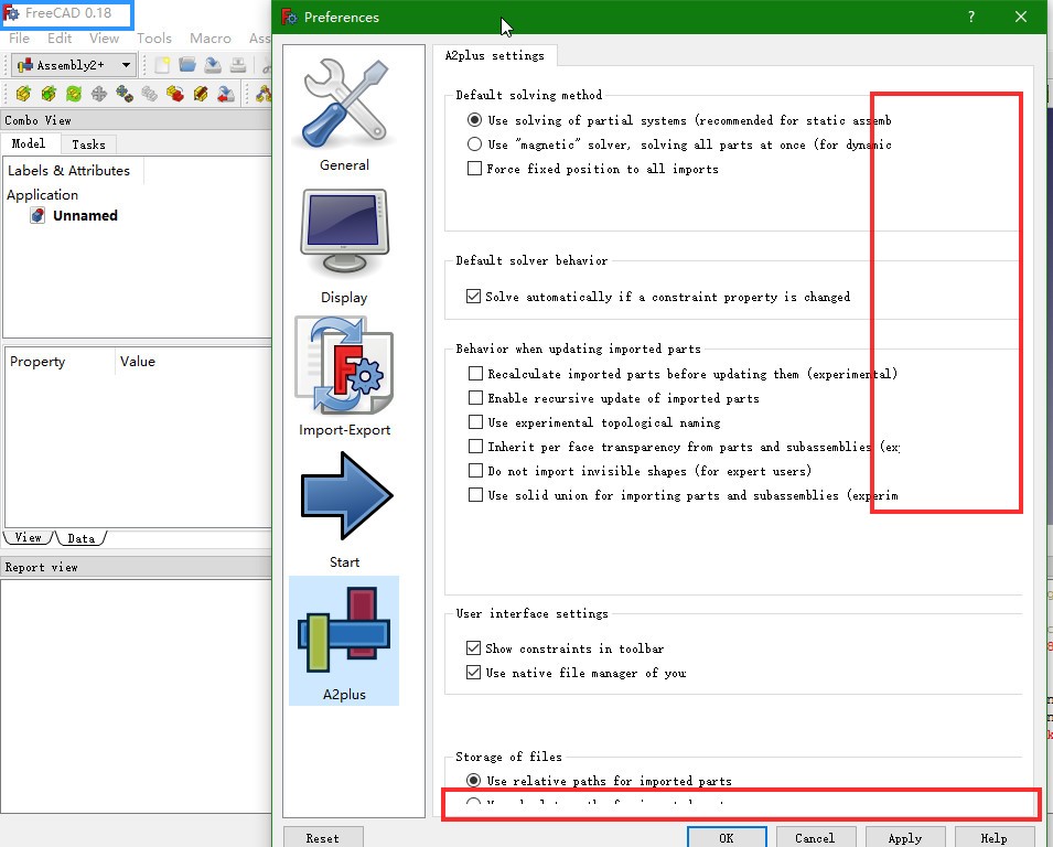
A minor UI bug of A2plus was found on fc 0.18.4/0.19pre (slightly different).
- On fc01.9pre, horizontal lines are truncated before end.
- On fc0.18.4, same as above. And no scroll bar on the right, so bottom line is truncated on the bottom.
Please take a look.

yikes, those fonts ![]()
I have a small question. I was collecting some documentation on the assembly workbenches to place on the wiki, so I was wondering if there was a single A2plus tutorial that you can consider a reference tutorial for learning to use this workbench.
It seems some users have prepared tutorials for Assembly3, and Zolko has written tutorials for Assembly4, so I was wondering if there is a basic, everybody-must-know tutorial for A2plus.
First documentation
There isn’t one within this form.
In case of help requests, i usually provide these two links:
- Documentation, which is always up to date: https://freecadweb.org/wiki/A2plus_Workbench
- A video with the basic A2plus workflow, the gripper assembly tutorial: https://www.youtube.com/watch?v=QMxcQ5tssWk
I think i will prepare a basic tutorial including all necessary parts at Github next time.
https://www.youtube.com/watch?v=7TUpS5Vani8&t=446
This is cool but the only thing that is cringe-worthy is the amount of superfluous mouse clicks and dragging are employed by the user. Notice how the Constraint dialog keeps getting moved by the user.
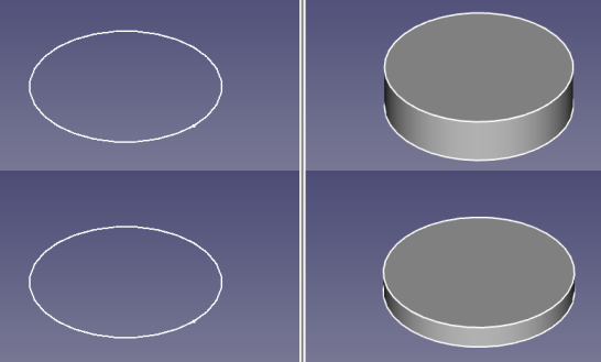
Hi @kbwbe

If i remember correctly this was already discussed to some extent, but i currently don’t remember the details. Will therefore just ask. Any chance of making circular edge constraint to work in such scenarios? It is obvious on why it currently doesn’t work, no shape.
Any opinion on this?
The key is to be able to find the selected object hierarchy. The following code will print out the current selected object hierarchy and obtain the shape at the correct placement.
import Part
for sel in Gui.Selection.getSelectionEx('', 0):
	for sub in sel.SubElementNames:
		print('%s.%s' % (sel.Object.Name, sub))
		Part.getShape(sel.Object, sub, needSubElement=True)
Thanks for providing the feedback and the code snippet example.
Hi @triplus,
basicaly, that’s possible. But parts of A2plus have to be redesigned. So the loadSystem() function of the solver must be made capable to handle the more complex object structure. Also all code which relates to selections has to be replaced by something like the code snippet of @realthunder, shown above.
Doing so, this will end up in a new WB which probably will not be compatible with the “old” A2plus.
kbwbe, I changed more in the “a2p_solversystem” I took and added some more ideas for checking constraints and stuck everything in the a2p_solversystem file. After finding the first constraint it checks every constraint on that part to see which is causing the conflict. I probably missed something but I think the basic concept is there. I also changed the message box so a person can check constraints without closing the form. We can also copy paste the names to another file.
Just drop the a2p_solversystem.py in and start you Rubics cube.
PS. save a backup first.
Dan.
I hope this works.

a2p_solversystem.py (35.6 KB)
Thanks for the explanation and i guess i see the dilemma. A lot of work involved and hard to maintain the backwards compatibility. As i currently use A2plus the most, for my assembly needs, workflow without using Links it is then.
Hi Dan,
thanks for all your work. I took up your ideas and implemented a new command to A2plus, in order to find the conflicting constraints.
Updating to new version A2plus V0.4.47, you will find this new button:

This command solves the constraints one after another and is showing the first conflicting constraint which can be deleted instantly, if wanted.
I hope it works.