Path Pocket Shape: 4th-axis Integration

Greetings FreeCAD users.
I would like to dedicate this topic to the integration of 4th-axis into the Path Pocket Shape tool in the PathWB.

I have attached the two modified scripts; you need both. Place them in your FreeCAD/Mod/Path/PathScripts directory, AFTER renaming your originals for safe keeping. Rename the new scripts to the original script names. Restart FreeCAD and have fun. I do not know how far backwards compatibility will work. Use at your own risk.

There is an existing bug related to the Extension Corners feature. Selecting a face that requires rotation (4th-axis) will cause an error, removing an unacceptable face(s) from the new operation. Simply double click on the same operation, go to the Base Geometry tab in the task window for the operation, select the face, add it to the list, then click OK. This should give you the desired operation. You might have to repeat this process, or click the blue recompute icon.
I think, in order to correct the related error, we will also have to integrate the 4th-axis pre-rotation into the Extension Corners code sections.

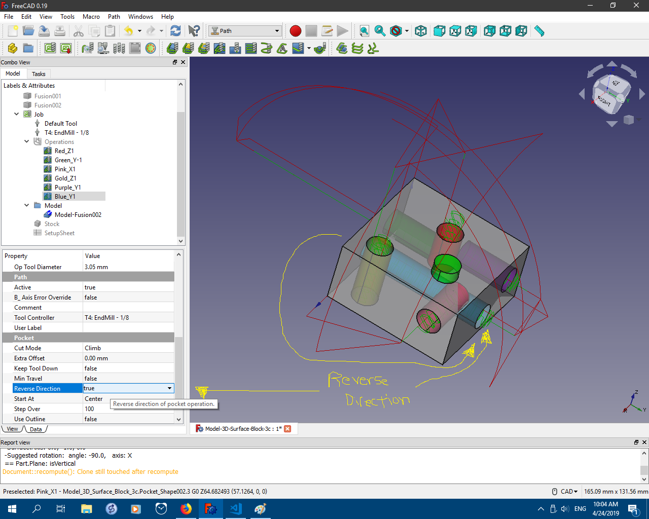
There is a temporary property, “B_Axis Error Override,” in the Path property section. Set to TRUE if you wish to align B-axis(Y-axis) rotations with the model for inspection purposes.
UPDATE: 2019-05-12 This will make these rotations look wrong in FC versions older than pre_0.19.16653 roughly, but will be correct in the real world. Versions released after PR #2114, roughly pre_0.19.16653, will render B-axis(Y-axis) rotations correctly with this property set to FALSE.
Regardless: Set “B_Axis Error Override” to FALSE before exporting gcode !

There is a “Reverse Direction” property in the Pocket property section. Should you need the pocket path orientation reversed (flipped 180 degrees), set this to TRUE. Hopefully this will yield the desired result.

Path Pocket Shape 4th-axis Usage:
To use the 4th-axis feature, do the following.

  1. Click on the Path Pocket Shape icon to start the operation.
  2. Click the OK to create the operation - no faces selected
  3. Select the new Pocket_Shape operation in task window
  4. In the operation’s Properties list, scroll to Path section and change the “Enable Rotation” property to the desired 4th-axis setting.
  5. Re-compute the operation
  6. Double click on the same operation, to edit settings in the task window.
  7. Open the ‘Base Geometry’ tab. Select one face (preferred at the moment) and click the ‘Add’ button, placing that face in the Base Geometry list.
  8. Change the other operation settings as desired.
  9. Click OK to save and apply the changes.

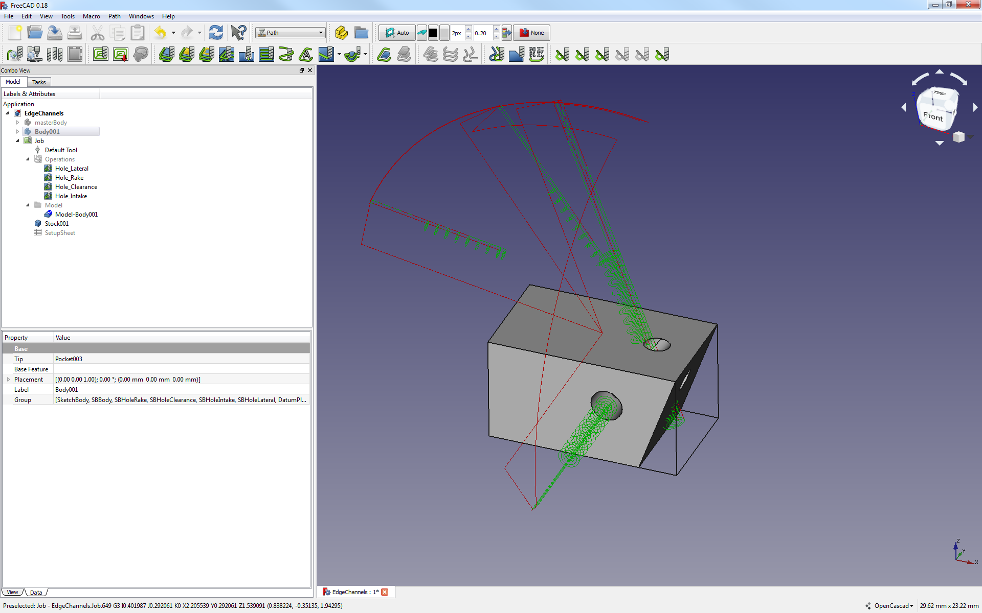
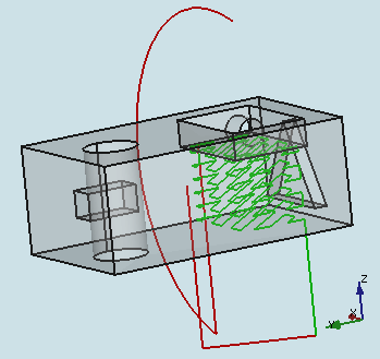
I appreciate the help testing the code. Please post pics, source model files and FC info when posting feedback. This is looking better every time!

Thanks,
Russell

UPDATE: 2019-04-26 Version 1f_testing uploaded :: should respect XYZ linear Model translations in Job setup; added axis selection property
UPDATE: 2019-04-30 This topic is also related to PR #2114.
UPDATE: 2019-04-30 Updated scripts to Rev. 1h Testing. Same version as currently in the PR. Repaired broken Profile Faces and Mill Faces operations based upon PathAreaOp.py script. Also addressed depthparams issue detected by @Sliptonic via Mill Faces op.
UPDATE: 2019-05-06 Updated PathPocketShape.py script to Rev. 1i Testing. Thanks to @RatonLaveur for identifying broken multi-face selection in Geometry tab of operation settings. Now fixed. Issue remains with tool controller.
UPDATE: 2019-05-12 Updated both PathPocketShape.py and PathAreaOp.py scripts attached to versions just copied from FC master since being committed in PR #2114.
UPDATE: 2019-06-01 Updated both PathPocketShape.py and PathAreaOp.py scripts attached to version 1k-testing. Fix for random repositioning of job model. Now creates additional clone per axis_angle rotation for basis of rotational pockets, then destroys temp clone used. You will need to re-create Path_Shape operations because the “Use Rotation” property is renamed “Enable Rotation” to prepare for UI integration.
UPDATE: 2019-06-01 Updated both PathPocketShape.py and PathAreaOp.py scripts attached to version 1k-testing-patch. Cleaned up code a bit and adapted for more universal integration of 4th-axis into the PathWB.
UPDATE: 2019-06-11 Updated both PathPocketShape.py and PathAreaOp.py scripts attached to version 2f-testing. Simplified code related to 4th-axis. Fixed model repositioning issue. Same version as PR #2231.
UPDATE: 2019-06-13 Updated both PathPocketShape.py and PathAreaOp.py scripts attached to version 2g-testing. Made some fixes pointed out by the involved and active @RatonLaveur. Additional cleaning of code and other feature tweaks.

UPDATE: 2020-10-06
Since the last update above, there have been a few additional improvements and fixes to the PathPocketShape module pertaining to 4th-axis. The scripts mentioned in the intro above are removed from this post and the master branch contains the most current version of the PathPocketShape module as related to this particular thread.


OS: Windows 10 (10.0)
Word size of OS: 64-bit
Word size of FreeCAD: 64-bit
Version: 0.19.16886 (Git)
Build type: Release
Branch: master
Hash: ed47e962d2c821bf1792889f6d7bdf457dcf6c9e
Python version: 3.6.8
Qt version: 5.12.1
Coin version: 4.0.0a
OCC version: 7.3.0
Locale: English/United States (en_US)
PathPocket-4th-axis_1d-C.png
PathPocket-4th-axis_1d-B.png
PathPocket-4th-axis_1d-A.png

Hello,

i tried it and completly failed :smiley:
What am i doing wrong?

OS: Ubuntu 19.04
Word size of OS: 64-bit
Word size of FreeCAD: 64-bit
Version: 0.18.1.
Build type: Release
Python version: 3.7.3
Qt version: 5.12.2
Coin version: 4.0.0a
OCC version: 7.3.0
Locale: German/Germany (de_DE)
4th_Test.FCStd (46.6 KB)
Bildschirmfoto von 2019-04-24 17-34-16.png

Hello,

I opened your file. I found a part of the problem in the job setup. The paths you see are based on the Body object, not the Model object. I don’t know if this is related to the code modifications or was pre-existing. I recall a similar issue existing with the 3D Surface operation. I’m short on time, but I’ll get back to you.

If you toggle visibility of the Body to on, and the Model in the Job to off, you will see two of the three operations align to the Body object. The top pocket needs “Reverse Direction” flag set to TRUE in the properties.

mfg
Russell

Thx, now it looks much better! Didn’t thought about this problem, since all ops are usually based on the model :slight_smile:

The rest looks good, only the starting depths seems a bit high.

mfg

Hi, I really enjoy reading your posts, to the point that I am starting to be concerned for my F5 key. :slight_smile: thanks a bunch for the work you are doing!. Looking forward to a time where I can revive my china 6040 4 axis and have a play with this. For the time being it feels like, all I have time to play with is diapers :slight_smile:

Hi Russel,

great work!
I’m thinking about building a new (a bit bigger) CNC router since a while, - it seams it has to have 4 axis (at least). :wink: :wink:

Dos this working without OpenCamLib? because i still have probs to get it run…

Evening,
I have investigated the problem of the paths not aligning to the Model. It is within the new, modified code. I have to apply the translational adjustments of the Model in the Job setup into the rotational translations for the pockets. This is a little challenging… :wink:

Starting depths currently are calculated with about three variables, some of which include the rotational limits of the Model. I can adjust them.

Russell

And could you please add the option to select the used Axis like “A” or “A and B”? Not everyone has 5 Axis :wink:

Mfg

Good day,
I have addressed the issues you identified - at least my tests have positive results.

The pockets should now respect the XYZ translations available in the Job setup. I have not attempted to use the rotation adjustments in the Job setup. Also, I adjusted starting height calculations.

I have attached your same file, with results using these adjustments mentioned.


Done. The default is “A & B”.

Just remember you will have to use the “Reverse Direction” property in some cases due to face orientation.

I will update the scripts in the initial post for this topic when I get back home.

Thanks for the help.
Russell
4th_Test_1f.png

Thanks, Herbk.
I don’t think that OCL is required; however, when I attempt to load the PathWB without OCL, I receive an error and the tools do not load. It appears there is a dependency error thrown for PathWB in general if OCL is unavailable. I’ll try to run more tests and investigate further.

Russell

One just potty trained and working on the second…

Thanks!
Russ

Hello gents,

Russ, I’ve been trying out the new options and they fit just right.

The B-axis override is fantastic to visualize the correct path in FreeCAD…of course, it means that the actual NC code viewed with NCviewer is all scrambled :slight_smile:

I’ll play around with the B and A axis selections. Thanks a lot!

As soon as i’m comfortable enough with this, I’ll definitely machine something and show :slight_smile:
EdgeChannels.FCStd (185 KB)
WithoutBAxisOverride.png
WithBaxisOverride.png

Good evening, Mates.

REMEMBER: Toggle all “B_Axis Error Override” properties to FALSE before exporting gcode for your machine.
This will leave B(y) axis rotations to appear incorrect in FreeCAD, but should be fine in the real world and NCViewer and Camotics.


This “Use Rotation” property will need some adjustments within the code. I don’t think it functions quite as smoothly as we would like. It does, nonetheless, provide the intended result within my limited testing.


I have updated the scripts attached to the initial post of this topic. Version 1f_testing should respect XYZ linear translations done within Job setup. Also, a property to select the rotational axis is available.

Thanks for the feedback gentlemen! Proceed with caution and the correct feeds and speeds… :slight_smile:

Cheers,
Russell

I finally had some time to look at your changes and I might be doing something wrong (I usually do). Attached file results in the following Path:
Capture.PNG
The pocket is in the positive Z direction and doesn’t need any rotation. There’s also something funny with the depths happening. Regardless of what I set the “FinalDepth” to it gets reset to being -10 during the recompute. And although “StartDepth” is at +22 the actual path starts at -22.

This is great stuff - I love it!
4th-axis.FCStd (57 KB)

Afternoon, MLampert.

Please don’t be upset. I opened the file, toggled the “Reverse Direction” property, and recomputed. Wha-lah.

This is an issue perhaps your expertise or @Sliptonic, or @JoshM, or another one of the many FC contributors could help me solve.

I don’t know if FreeCAD, NO, if I have the know how to tell FreeCAD how to identify the direction of any pocket toward the exterior of the Model. From looking at your model, and based on usage of FreeCAD, and developing this script modification, I bet that your pocket in question was made by setting a cube, right-side-up, atop the body and doing a cut operation. This would leave the bottom face of that cube as the bottom of the pocket. This is the result of the script’s analysis of that face using face.Surface.Axis: value is probably -Z or (0,0,-1). Therefore, the script thinks the direction of the pocket should be down, -Z.

I haven’t taken time to figure out the algorithm needed to correctly orient any pocket’s direction toward the outside of the Model. So… I have the “Reverse Direction” property for just these cases. At this, point, I think allowing the user to simply “Reverse Direction” of the pocket seems the easiest solution, and less difficult to code. If I find time, I may look into such an algorithm improvement. It would be great for certain!

+1 !

Let the chips fly, amigo.
Russell
4th-axis_Reverse-Direction.png

Morning FC Users,
I just posted updated versions of the two scripts involved in the Path Pocket Shape 4th-axis integration; they are available with the initial post of this topic. Some errors have been corrected:

  • Fixed broken PathWB operations related to PathAreaOp.py script: Tuple size differences in return values from Profile Faces, Mill Faces, and other tools based on PathAreaOp.py script are fixed. The affected tools seem to be back in action.
  • Depth parameter issue reported by @Sliptonic has been addressed. Tests results are correct, so far.
  • You might need to delete and recreate any Path Pocket Shape operations you have, after you install these scripts.

Thank you for testing and reporting errors.
More good news: @Mlampert and I agree we have found the missing negative sign to make the B-axis rotations render correctly in FC. Well, @Mlampert probably knew all along, where as I had to fumble around and backtrack code with python sniffing dogs trained from birth. But, that is beside the point. Initial testing after compiling the corrected code yields positive results. Thanks, @MLampert for all your coding contributions and other help! Once we get the correction committed to the master branch, the 4th-axis scripts we have been testing can be edited to remove the “B-axis render override” flag. Hallelujah!

Later,
Russell

Gentlemen,

I was rubbing my hands with the added file, hoping to check for capabilities and interesting behaviors.
To my surprise, the 3D pocket is now behaving as if Russ had not performed his magic over last few weeks.

I’m using both of the most up-to-date files in the original post of this thread (rev. i usable)

Is there something I’m missing?

OS: Windows 7
Word size of OS: 64-bit
Word size of FreeCAD: 64-bit
Version: 0.18.16093 (Git)
Build type: Release
Branch: releases/FreeCAD-0-18
Hash: 690774c0effe4fd7b8d2b5e2fb2b8c8d145e21ce
Python version: 2.7.14
Qt version: 4.8.7
Coin version: 4.0.0a
OCC version: 7.2.0
Locale: French/Switzerland (fr_CH)
2019-05-16_13h29_08.png
MultiHolePolar.FCStd (65.2 KB)

Evening RatonLaveur,
I opened your file. I see the problem - one of them.

It looks like you used the 3D Pocket tool originally. It does not support 4th-axis, yet. You need to use the Path Pocket Shape tool - circled in the attached image.

28 May 2019: Moved usage instructions to initial post in topic.

Submitting this model for assistance here in the forum has also exposed another error in the existing code. Pocket_Shape 4 is missing, as seen in the image. The operation is present, but no path is made. This is an error in the face analysis algorithm in the code; this pocket is mistakenly identified with the following error>> PathPocketShape.ERROR: Pocket does not support shape Model-Body001.Face3. I will take a look at it and work to correct the problem. I do not know if it is related to the use of the polar array or some other analysis issue.

Thanks!
Russell
MultiHolePolar (1).FCStd (70.8 KB)
MultiHolePolar_1-Path_Shape-Use_Rotation.png

Hello Russ,

Thanks a lot. I don’t know how I have become inept at using it after playing with it for the last few weeks. Thanks for the help.

Yes the model i made to really push the boundaries of what the 4th axis can do. It’s parametric, you’ll notice. That the holes are initially cardinal (aligned with X and Y) but all you have to do to make this into a nightmare is to add a few repetition on the polar pattern :slight_smile: then it’s compound angle…oh boy.

Cheers.

J.

Hello gents,

A little bit more feedback. Finally confident that I could use the 4th axis integration for actual testing in my 3+2 machine, I prepare a comparatively simple model: a square tip to be cut from square rod.

Fooling around with the options, the use of the Path Pocket shapes moves the model relative to the stock in a funny way. I see no reason why path pocket should move the work piece model that way.

To repeat the issue:

  1. open Job setup
  2. orient the tip to either X or Y axis (Z is now transversal to the feature main-axis.
  3. select one of the faces of the tip, and select the pocket based on face
  4. press apply (with intention of activating rotation of the A(x) and B(y) axis in the data tab afterwards.

What happens: the model moves relative the stock back to a main Z orientation.
Results are scrambled.

Strange strange.

Attached: pictures of what happens.
Attached: model to play with.
TipCutting.FCStd (26.4 KB)
OriginalIntendedOrientation.png
PocketingFaceReorientsPartUnduly.png