How about the following? New object App::FeatruePython. This object holds all properties for one analysis. For example type = frequency, modalformcount = 10 etc. or type = deformations (up to date we only have linear elastic but later we could have nonlinear etc …). A litte gui would be nice but it should be possible just with the standard FreeCAD properties and the FreeCAD PropertyEditor.
By starting an analysis the object will be evaluated and the appropriate CalculiXrun will be made. If there are two analysis objects one for deformations and one for frequency they both will be done one by one.
The old analysis butten with the gui for editing the calculix inputfile will work only with one selected analysis object.
The idea is per one analysis object we will have one CalculiX input file. With this it really make sense to splitt the input file in two files the mesh and all the rest.
Mhh lots of things… I know … Hopefully you got my point Przemo. I would even help with this. What do you think?
Hi, maybe what FreeCAD needs is a way to define a the kind of analysis when is created. I meant, one could press an icon to create a new analysis on the selected part, but now is hardcoded that the analysis will be static, I would preffer to have a way to choose between different types (starting from lineal static, no lineal static, modal, thermal…). Once the analysis is created maybe could exist another icons to add the needed “parameters” for them, just like now we have loads and restrains for the static, an extra icon could be created for adding the modal frecuency parameters needed, another for the thermal parameters, another for the nolineal static…
Now when we create a new analysis automaticly appears the parameters for the mesh generation, maybe in place should appear the choice for the analysis and parts to be analized.
About what Bernd says on splitting the input file in mesh and boundary conditions, is a great idea!!! Now with big meshes having to open and scroll down to the end take some time in case you need to edit manually. On the other side could serve as bassis to start with multibody analysis, as you can define the meshes for different parts and then just reference in the boundary condition input file.
Thanks! To be honest I don’t need it, but it looks so good that I had to code it
I changed maximum allowed deformation from 10% to 0.1% - can you test if it’s better now?
I’m trialing with the FEM /mesh is it possible to mesh a plate as a shell so all elements have thickness of the plate.
I have now this kind of result and so i need more ellemens as i want
Another point is can i make serval calculations at the same time in one model multple forces/ materials or meshes
Hi, maybe you can create your model just as a surface and mesh it with the gmesh macro with 2d elements. Then you must edit manually the input file for defining the thickness propertie.
according to this link limits of low and high frequencies are possible
And link
FREQUENCY CALCULATIONS
mei[0] number of requested eigenvalues
mei[1] number of Lanczos vectors
mei[2] maximum number of iterations
mei[3] if 1: store eigenfrequencies, eigenmodes, mass matrix and possibly stiffness matrix in .eig file, else 0
fei[0] tolerance (accuracy)
fei[1] lower value of requested frequency range
fei[2] upper value of requested frequency range
Hi, maybe you can create your model just as a surface and mesh it with the gmesh macro with 2d elements. Then you must edit manually the input file for defining the thickness propertie.
Regards
Have some patience, this will be possible by the gui soon !
Thanks for pointing that out! I’ll include frequency limits in my test branch, but I don’t think mei[0] has any value for us - it’s an internal ccx variable. Please correct me if I’m wrong.
It’s easy. If you can pull that branch and compile FreeCAD it’s just a matter of opening python console View->Views->Python console and typing line by line (or copy & paste)
Thank you for developing this nice feature for FreeCAD.
I am looking forward to see this in master.
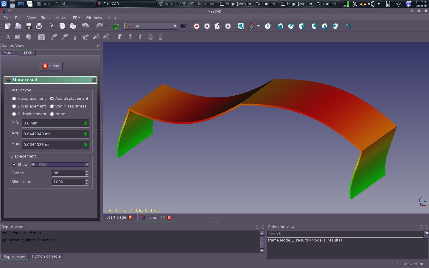
What I miss most is having the eigenfrequency values listed as Hz in the GUI when showing the ‘results information’ and limiting the number of eigenmodes to calculate. Additionally I am not sure if the stress is plotted correctly for each eigenmode.
Hi Howil,
Thanks for testing! Limiting the number of modes is possible from python. See my previous posts. The stress doesn’t seem t be right, you are correct.
To get the eigenfrequency values in GUI we have to write .dat file reader first. It’s not hard, but it takes time (I can help if someone is willing to code it)
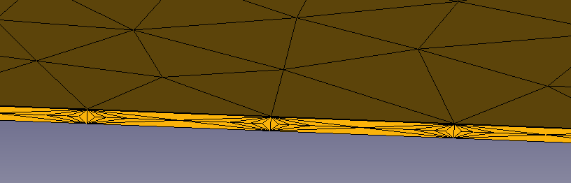
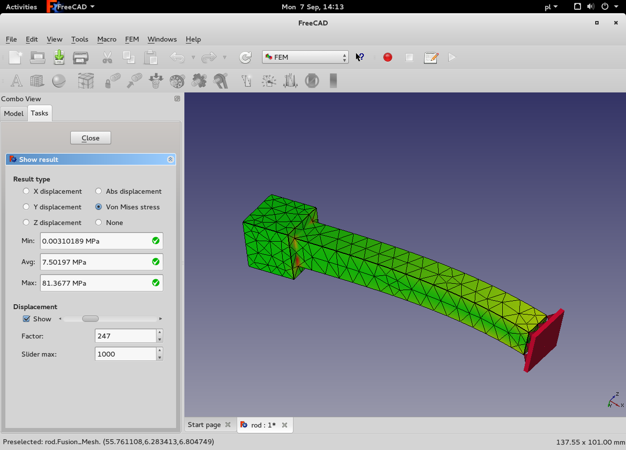
There is a solver problem or a scaling problem. Some stress values are very high and they are skewing the colors. I.e. min stress ~0 MPa, average 7.5 MPa, and max 81 MPa. As the result most of the stress is close to the lower end, so it looks invalid. There are also a few hot spots and a hint of yellow along the main part of the beam suggesting that the results are good, except the hot spots (see attached picture). I’m not sure how to solve that problem. I could implement a cut-off value to get the colours right, but that’s a workaround not a solution.
Edit: Using finer mesh is giving even worse results: 0 MPa/8 MPa/ 185MPa
Hi, does the stress calculation have some meaning on the modal analysis? If the displacements are not really accurate, how could be the stress accurate? Normally we never give importance to the displacement value, we only see the shape of the part at the Eigen frecuencie (and obviously the frecuency value)
If we want to see how much a part will move at the resonances frecuencies, what we do normally is a second analisis called “modal superposition”, taking the Eigen values of the first calculus and appliyng an impossed displacement to the estructure (what would be an external exitation in the real world). Then the results of this calculation has the real displacements for the estructures amplified at the resonant frecuencies (if the exitation displacement is in the same direction as the movement of the part at the first calculus)
PD: I’m not a theoric of the dynamic analysis, so, feel free to correct me, but have made lot of modal FEA and real testing in the past
Steel flat beam 100x10x2 mm mode 1 stress looks OK
Some very fine mesh calculations shows that we’re reading the data from .frd file correctly, so it’s a solver problem that we might have to handle using a cut-off value as suggested by sgrogan