The approach is to take the method PD Loft uses to take care of inner wires. However I am stuck and after 3 hours I have to give up for now and I hope that you can join me. I hope a fresh look from outside might reveal my mistake.
I made some more modifications to the PR, just for debugging purposes. Here is the diff:
--- src/Mod/Part/App/FeatureExtrusion.cpp
+++ src/Mod/Part/App/FeatureExtrusion.cpp
@@ -28,9 +28,12 @@
 # include <gp_Trsf.hxx>
 # include <BRepAdaptor_Surface.hxx>
 # include <BRepAdaptor_Curve.hxx>
+# include <BRepClass3d_SolidClassifier.hxx>
 # include <BRepOffsetAPI_MakeOffset.hxx>
 # include <BRepBuilderAPI_Copy.hxx>
+# include <BRepBuilderAPI_MakeSolid.hxx>
 # include <BRepBuilderAPI_MakeWire.hxx>
+# include <BRepBuilderAPI_Sewing.hxx>
 # include <BRepOffsetAPI_ThruSections.hxx>
 # include <BRepPrimAPI_MakePrism.hxx>
 # include <Precision.hxx>
@@ -45,6 +48,8 @@
 #endif

 #include "FeatureExtrusion.h"
+#include <App/Application.h>
+#include <App/Document.h>
 #include <Base/Tools.h>
 #include <Base/Exception.h>
 #include "Part2DObject.h"
@@ -612,16 +617,28 @@ void Extrusion::makeDraft(const ExtrusionParameters& params, const TopoDS_Shape&
             TopoDS_Shape front = shape;
             front.Move(invObjLoc);
             sewer.Add(front);
+            Part::Feature *front_feature = static_cast<Part::Feature*> (App::GetApplication().getActiveDocument()->addObject("Part::Feature","front"));
+            front_feature->Shape.setValue(front);
             std::vector<TopoDS_Wire> backwires;
-            for (auto& wires : extrusionSections)
+            for (auto& wires : extrusionSections){
                 backwires.push_back(TopoDS::Wire(wires.back()));
+                Part::Feature *wire_feature = static_cast<Part::Feature*> (App::GetApplication().getActiveDocument()->addObject("Part::Feature","wire"));
+                wire_feature->Shape.setValue(TopoDS::Wire(wires.back()));
+            }
             TopoDS_Shape back = Part::FaceMakerCheese::makeFace(backwires);
+            Part::Feature *back_feature = static_cast<Part::Feature*> (App::GetApplication().getActiveDocument()->addObject("Part::Feature","back"));
+            back_feature->Shape.setValue(back);
             sewer.Add(back);
-            for (TopoDS_Shape& s : shells)
+            for (TopoDS_Shape& s : shells){
                 sewer.Add(s);
+                Part::Feature *shell_feature = static_cast<Part::Feature*> (App::GetApplication().getActiveDocument()->addObject("Part::Feature","shell"));
+                shell_feature->Shape.setValue(s);
+            }

             sewer.Perform();

+
+
             // build the solid
             BRepBuilderAPI_MakeSolid mkSolid;
             mkSolid.Add(TopoDS::Shell(sewer.SewedShape())); // <- Building the extrude fails here
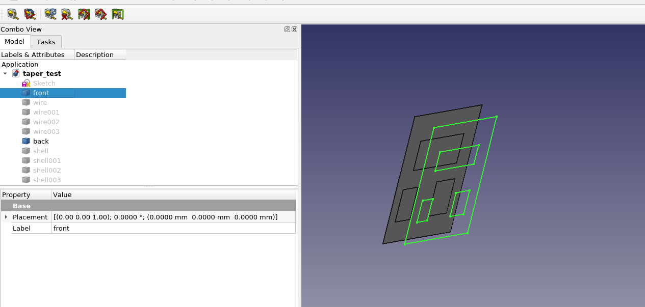
These lines are equivalent to in python:
Part.show(shape,shapename)
Except for the “wire” objects, these are the objects added to the sewer object. The wires are used to build the “back” face. These wires look fine, but the “back” face is not valid. It has self-intersections and is really just a compound of faces made from the various wires. The “front” shape is not a face at all. The shells are all solids and check out okay. taper_test.FCStd (28 KB)
Many thanks! This helped me to find one issue: one must perform the offset operation on the unmoved shape. Then it can be moved. This fixes the wires and also the back face.
It is probably better to follow PartDesign Draft than Loft. The attachment shows: While Draft creates Planes, does Loft create BSpline surfaces. This has in the past often lead to problems. LoftVsDraft.FCStd (16 KB)
Here in action:
As I feared, allowing inner wires opens Pandora’s box. On negative angles The OCC Kernel sometimes crashes, no matter how smalle the negative angle is. The crashes depend strongly on the inner wire position and size.
So for now I think when there are inner wires, we cannot support negative angles
I updated the PR to the method that was successful for PartDesign.
This still fails bit there is only one issue we need to resolve:
When you have a sketch with inner wires, the location of the inner wires is wrong. On making the offset, the location is correctly transformed the bug is that the initial location of the shape when making the offset is actually not the location of the shape in the document.
I fail to find out why this happens not how to restore the correct location.
However also for PD the same issue appears. When one for example makes a pad using the face of another pad as face, the inner wires also loose their location.
We must take a step back an evaluate our options before merging anything. We should consider RTs implementation and also chrisbs suggestion.
It is a real pity if negative angle cannot be allowed.
Also the BSpline issue deserves consideration. Is it possible to click on a bspline face and make a sketch? If not, we would miss out on the most intuitive workflow (yes I know it is not good practice).
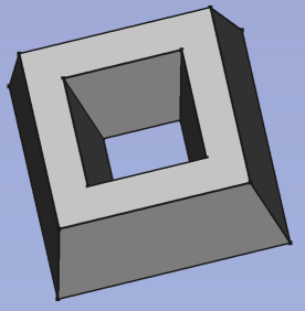
Draft is no option. This is applied on faces - a nightmare because of toponaming. Moreover you need several draft operations to get your example. Furthermore you cannot draft to a result I showed in the first image of https://forum.freecadweb.org/viewtopic.php?p=560422#p560422
Extrude is already doing it right - building shells from the sketch wires, the only thing we need to add is that it takes care of the inner wires. At the moment it takes the outermost wire only.
I don’t understand your concerns with B-Splines. What is the issue with this? Do people have issues with the existing Extrude features?
I will not change too much. Extrude is THE main feature when going from 2D to 3D therefore “never change a working method” applies here in particular.
You cannot make a sketch on a BSpline. So the most basic workflow of a feature based cad software vanishes. This may be fine for Part that can rely on CSG workflow. But for PartDesign it is not good.
I still don’t understand. Can you therefore explain it a bit more please. Where do you need to make the sketch that you cannot do?
Most of my real-life sketches contains B-Splines (I even wrote this Wiki page: https://wiki.freecadweb.org/B-Splines ). B-Splines are a basic feature of CAD in my opinion.
Therefore I need to understand the issue properly.
Note that also @realthunder’s approach to implement tapered extrudes uses the same OCC method like the existing Extrude feature. Only the way he creates the top and back faced is different. However, as I understand @chrisb, the B-Spline issue is something with the shells, not the faces. @realthunder wrote that there is an option to create the shells in a different way, but also this one has drawbacks.
I don’t entirely understand, is it impossible to identify the faces that need to be drafted? can’t we extrude without making a solid, then draft all faces and then generate the missing 2 faces? TNP shouldn’t affect this.
The draft feature is applied to a face and the face number changes during the design process. Therefore I never use drafts in real-life documents anymore. It is just pain to repair the drafts again and again (like with fillets).
However, we speak here about different things. The important thing is how the shells are built with the OCC kernel. There is a difference in getting wires (the technical term of OCC for closed paths) or taking an existing face and modify it.
If this the desired behavior, can implement it this way. Note however, as I found out, the OCC kernel has problems to shrink small wires - the smaller e.g. the diameter of an inner circle, the more likely it crashes, no matter how small you make the negative offset (negative angle).
Therefore I am once more convinced that taking care of inner wires should be the second step for PD Pad/Pocket.
I guess this is the question. Would this be a workable way to implement the feature? Create the normal pad. Then modify it to have the taper?
I have not thought about it deeply. But it is an appealing thought that taper could be modified from 0, and still have the same face numbering and face types.
In the current version of OCC it is indeed possible to attach sketches to flat BSplineCurves. However, I would not rely on that. Furthermore I guess that BSplineCurves will raise many more coplanar issues, that plane faces would do.
I have to admit that I am getting tired of this. It takes quite some effort to creata all of these finally useless counter examples. If I see it right it boils down to a decision between having
simpler implementation at the cost of more complicated models - and a BSplineCurve is more complicated
vs. simpler models at the cost of a more complex implementation.
I would always prefer the latter, because it’s the models I want to keep. (Off topic: I don’t store summer clothes over the winter without having them washed).
And I dare to doubt that using the already existing Draft technique is really more complex than creating a loft.
There are more limitations of b-splines. For example while projecting (or sectioning) in 2D, then a plane is no line more. Setting sketches on it is mentions from other above. You can not use it as reference for a mirror or other planes basis and so on. So the usecase is then pretty limited.
To be honest, this is not, at least for me, a valid argument. Because
then it is no extrude/pad
a draft is or can be more capable then a in build extrude/pad draft function, because it is their main function
it is a obsolete function, when the TNP is solved. What will you do when then? Then you have duplicate functions in FreeCAD. When deleting the functions, maybe then the documents are not backwards compatible
it messes the body tree, on larger objects the searching for the correct parametric to change is a nightmare in build in functions
( - FreeCAD should act like there is no TNP, but this in only my strange opinion)
I will not be unthankful, you made very good changes in FreeCAD, they i really appreciate! Thanks for that!
You are right, that draft currently is a toponaming nightmare. But even more so would a non breaking replacement be very welcome. I am not sure, if draft is no option, because all of this would be done in a siingle operation. And there you have it in your own hands to use the right faces. If it is all done in a single op, it may work, if it is done in two it can break.
The same holds for the example with the different angles in both directions. While you are creating it, you can well iinsert the necessary seams.