fem analisys on carbon tube specs?
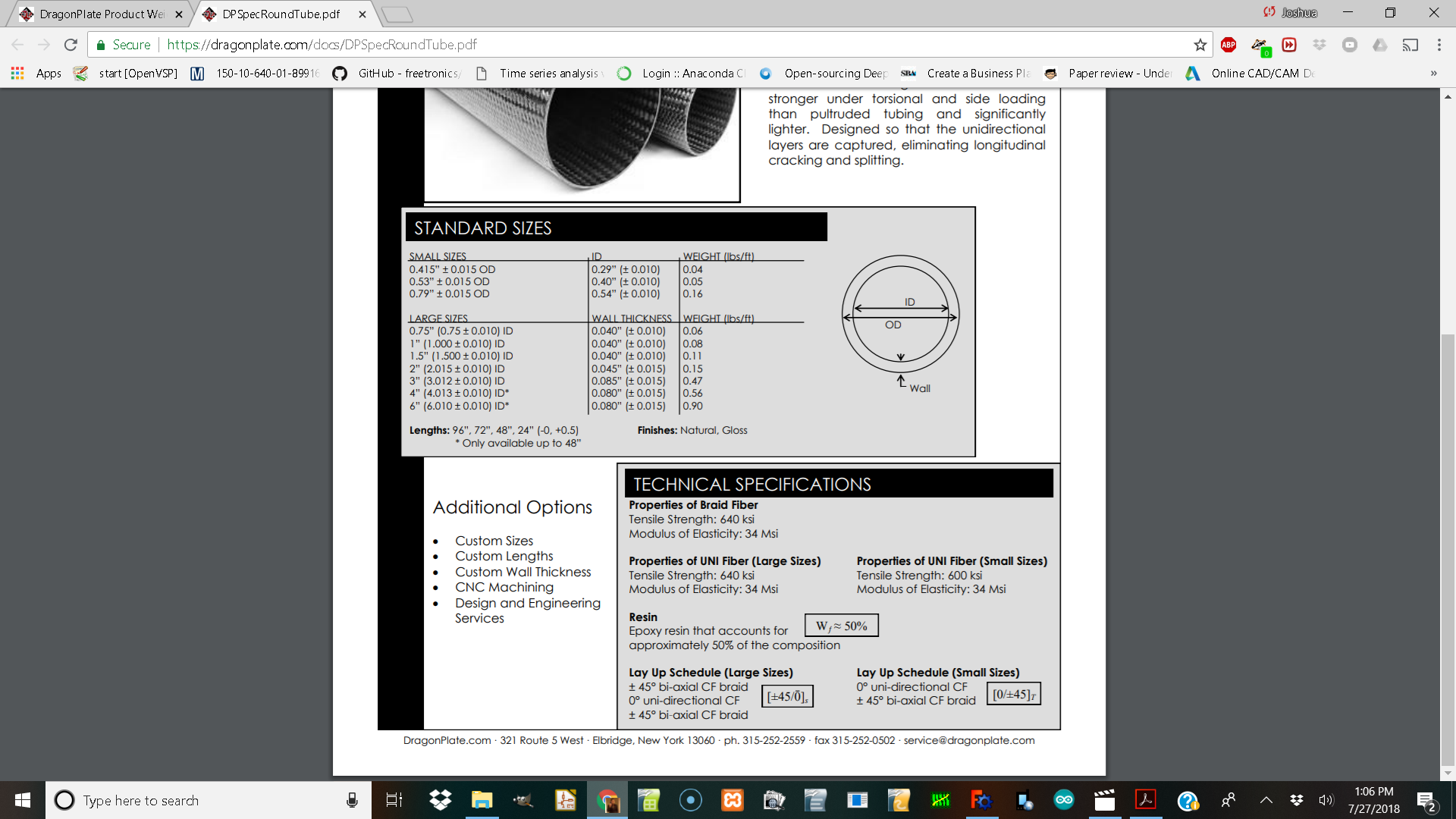
I am looking at the specs page of dragon plate and want to design something with it but do not know how to get their specs into freecad for puting forces on them?
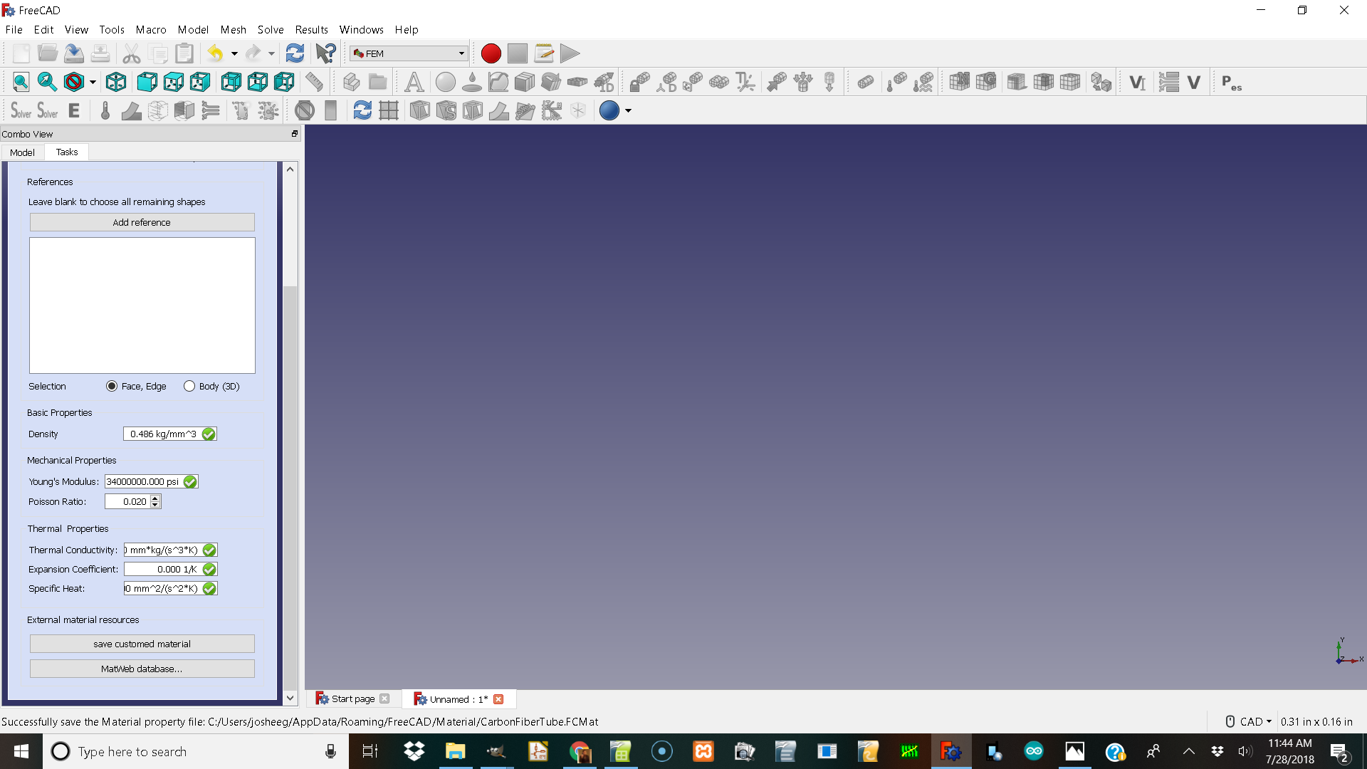
I have gotten fem to work just now I need to make a material.
If I understand well you’re question, you just have to find the :
density (kg/m3) (you can have it from your picture with the weight, the inner and outer diameters)
I’m not familiar with british units, but you might find a density in kg/m3 with the formula :
D = 2.76799e4 * W / (12PI((OD/2)² - (ID/2)²)
With W the weight in lbs/ft ; OD and ID in inches
Young Modulus (GPa) (it’s a Elasticity modulus on the datasheet, just convert the msi to GPa)
34msi = 234 GPa
Poisson number (-) it’s always the most difficult data to find.
Let’s say 0.2 is a good guess for carbon/resin composites
When you’ve got all that, you can take any of the material proposed in the FEM material menu and change it’s properties.
You can then save it with the “save custom material” button.
Oh, you don’t have the same units than I have in freecad !
I did forgot that we don’t have all the same settings…
That part seems ok, but I’ve got a doubt for your density.
Usually carbon/resin composites are heavier (density of water is 1000 kg/m3, I think you should find around 1500 kg/m3 = 1.5E-6 kg/mm3)
I’ll do some math to see want I get !
EDIT : I did some “maths”
ID = 0.4" = 0.01016 m
OD = 0.53" = 0.013462 m
W = 0.05 lbs/ft = 0,0744082 kg/m
Then, the surface of the tube section is S = pi*((OD/2)^2 - (ID/2)^2) = 6.126093.1E-5 m2
And D = W/S = 1214.6 kg/m3 = 1.2146E-6 kg/mm3
When I put in 0.0000012146 under kg/mm3 the numbers blank out to 0.00
Is it too large of a number?
THe material I make doen’t seem to want to hold the values and I can’t go back to check after I select ok for the material except make a new one.???
I tried that material to analyse a tube and I get a gmesh error
0.0: We are going to start …
0.1: Start Gmsh …
3.6: Gmsh had warnings …
3.7: Error : Self intersecting surface mesh, computing intersections (this could take a while) Error : Could not open file ‘intersect.pos’ Warning : Volume 1 consists of no elements Warning : OCC Project Point on Surface FAIL Warning : OCC Project Point on Surface FAIL Warning : OCC Project Point on Surface FAIL Warning : OCC Project Point on Surface FAIL Warning : OCC Project Point on Surface FAIL Warning : OCC Project Point on Surface FAIL Warning : OCC Project Point on Surface FAIL Warning : OCC Project Point on Surface FAIL Warning : OCC Project Point on Surface FAIL Warning : OCC Project Point on Surface FAIL Warning : OCC Project Point on Surface FAIL Warning : OCC Project Point on Surface FAIL Warning : OCC Project Point on Surface FAIL Warning : OCC Project Point on Surface FAIL Warning : OCC Project Point on Surface FAIL Warning : OCC Project Point on Surface FAIL Warning : OCC Project Point on Surface FAIL Warning : OCC Project Point on Surface FAIL Warning : OCC Project Point on Surface FAIL Warning : OCC Project Point on Surface FAIL Warning : OCC Project Point on Surface FAIL Warning : OCC Project Point on Surface FAIL Warning : OCC Project Point on Surface FAIL Warning : OCC Project Point on Surface FAIL Warning : OCC Project Point on Surface FAIL Warning : OCC Project Point on Surface FAIL Warning : OCC Project Point on Surface FAIL Warning : OCC Project Point on Surface FAIL Warning : Surface mesh: worst distortion = -6.45584 (avg = 0.500218, 44 elements with jac.
3.7: Gmsh done!
If you fill it just like this :
It will be correct.
NB : on my version I put 34000000 psi as a young modulus and it has been automatically converted into GPa.
Mine did not convert but I have 17 you may have 18 and yours has the fields displayed differently.
I would like to know how and why other people added other materials and how they saved it in here.
If I have to make the shape out of cubes I will but has anyone used cilanders in freecad fem?
Also has anyone gotten the shell part of fem to work to see how my tube frame would be effected by forces.
That is very interesting!
I got it to make the solution mesh and colored it with abs displacement and displacement checkbox and slider.
So it seems to have a shell
is made of some material it says aluminum looking at its features we might be able to do it with calculix steel.
The fem constraint displacement is different from me trying the lock shaped.
I tried fixing the end face of your cylander and it seems like it is hollow?
I looked at the components it was modeled with. It doen’t look like draw a circle and extrude to tube?
Apparently, you’re trying to use shell elements. Shell elements are used on surfaces, not volumes (the idea is to tell the solver that the faces have a “thickness” to represent a volume).
If you want to do a simulation on your cylinder, you must not use shells but real 3D elements (like the cantilever 3D example).
Well If I start with a circle give it a radius pad it.
set the diameter
set the pad
run fem on it as a 3d object I get a error
.0: We are going to start …
0.1: Start Gmsh …
2.7: Gmsh had warnings …
2.7: Error : Self intersecting surface mesh, computing intersections (this could take a while) Error : Could not open file ‘intersect.pos’ Warning : Volume 1 consists of no elements Warning : OCC Project Point on Surface FAIL Warning : OCC Project Point on Surface FAIL Warning : OCC Project Point on Surface FAIL Warning : OCC Project Point on Surface FAIL Warning : OCC Project Point on Surface FAIL Warning : OCC Project Point on Surface FAIL Warning : OCC Project Point on Surface FAIL Warning : OCC Project Point on Surface FAIL Warning : OCC Project Point on Surface FAIL Warning : OCC Project Point on Surface FAIL Warning : OCC Project Point on Surface FAIL Warning : OCC Project Point on Surface FAIL Warning : OCC Project Point on Surface FAIL Warning : OCC Project Point on Surface FAIL Warning : Surface mesh: worst distortion = -0.735409 (avg = 0.776081, 18 elements with jac.
2.7: Gmsh done!
would you post the FrerCAD file? From your sceen I would assume you should use a finer mesh for your geometry. Set max elementsize in GMSH mesh object.
I am running windows 10 and freecad 0.17 and the max and min element sizes are 0.0 both of them that equals auto. But maby selecting the circle part and putting a force on it. does not mesh in gmesh ok because it is not closed manafold correctly. The outside identified or something?