Exactly! And this topic is not about starting right now some experiments (also if it would be cool), but more about exploring different approaches and ideas before writing code.
It’s just architectish chatting ![]()
I won’t expect any usable result emerging before 0.21 ![]() And by that time maybe @realthunder or others could also have solved the issue about 10k+ document objects in the scene…
And by that time maybe @realthunder or others could also have solved the issue about 10k+ document objects in the scene… ![]()
Yes it si an archive, a normal zip file, but someone, maybe realthunder as told me that is not very manageable as it is treated like a CVS file, (a sort of Github container), but is is easily inspected, it suffice that you copy a FCstd file and modify the extension in zip and deompress.
this a partial directory structure of a FCstd file decompressed, I have retained only some files to inspect them.
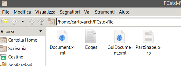
Yes it the Document.xml file
<?xml version='1.0' encoding='utf-8'?>
<!--
 FreeCAD Document, see http://www.freecadweb.org for more information...
-->
<Document SchemaVersion="4" ProgramVersion="0.16R6703 (Git)" FileVersion="1">
and with a structure like:
    <Objects Count="117">
        <Object type="Part::Compound" name="Compound" />
        <Object type="Sketcher::SketchObject" name="Sketch001" />
        <Object type="PartDesign::Pad" name="Pad001" />
        <Object type="Sketcher::SketchObject" name="Sketch002" />
        <Object type="PartDesign::Pad" name="Pad002" />
        <Object type="Sketcher::SketchObject" name="Sketch003" />
or
    <ObjectData Count="117">
        <Object name="Compound">
            <Properties Count="5">
                <Property name="ExpressionEngine" type="App::PropertyExpressionEngine">
                    <ExpressionEngine count="0">
                    </ExpressionEngine>
                </Property>
                <Property name="Label" type="App::PropertyString">
                    <String value="extruder-motor"/>
                </Property>
                <Property name="Links" type="App::PropertyLinkList">
                    <LinkList count="0">
                    </LinkList>
                </Property>
                <Property name="Placement" type="App::PropertyPlacement">
                    <PropertyPlacement Px="109.650000000000" Py="-100.500000000000" Pz="-442.000000000000" Q0="0.000000000000" Q1="0.000000000000" Q2="0.000000000000" Q3="1.000000000000"/>
                </Property>
                <Property name="Shape" type="Part::PropertyPartShape">
                    <Part file="PartShape.brp"/>
                </Property>
            </Properties>
        </Object>
And the properties, not the Placement that is internally stored as a Quaternion and the Shape that has the reference to the brp file that you could see in the directory image,
        <Object name="Sketch001">
            <Properties Count="8">
                <Property name="Constraints" type="Sketcher::PropertyConstraintList">
                    <ConstraintList count="29">
                        <Constrain Name="" Type="2" Value="0.000000000000" First="0" FirstPos="0" Second="-2000" SecondPos="0" Third="-2000" ThirdPos="0" LabelDistance="10.000000000000" LabelPosition="0.000000000000" IsDriving="1" />
                        <Constrain Name="" Type="2" Value="0.000000000000" First="2" FirstPos="0" Second="-2000" SecondPos="0" Third="-2000" ThirdPos="0" LabelDistance="10.000000000000" LabelPosition="0.000000000000" IsDriving="1" />
                        <Constrain Name="" Type="3" Value="0.000000000000" First="1" FirstPos="0" Second="-2000" SecondPos="0" Third="-2000" ThirdPos="0" LabelDistance="10.000000000000" LabelPosition="0.000000000000" IsDriving="1" />
                        <Constrain Name="" Type="3" Value="0.000000000000" First="3" FirstPos="0" Second="-2000" SecondPos="0" Third="-2000" ThirdPos="0" LabelDistance="10.000000000000" LabelPosition="0.000000000000" IsDriving="1" />
                        <Constrain Name="" Type="13" Value="0.000000000000" First="0" FirstPos="1" Second="4" SecondPos="0" Third="-2000" ThirdPos="0" LabelDistance="10.000000000000" LabelPosition="0.000000000000" IsDriving="1" />
                        <Constrain Name="" Type="13" Value="0.000000000000" First="0" FirstPos="2" Second="4" SecondPos="0" Third="-2000" ThirdPos="0" LabelDistance="10.000000000000" LabelPosition="0.000000000000" IsDriving="1" />
This is a partial part of a sketcher object.
Yes but the file is not binary, is a normal ascii file:
DBRep_DrawableShape

CASCADE Topology V1, (c) Matra-Datavision
Locations 7
1
              1               0               0          109.65
              0               1               0          -100.5
              0               0               1            -442
1
6.07291994469961e-014 -7.04991620636974e-015               1 -109.653354136413
              1 -1.149080830487e-014 -6.07291994469962e-014 100.500689864652
1.14908083048704e-014               1 7.04991620636904e-015 465.263548454841
2  1 -1 2 -1 0
1
6.07291994469961e-014 -7.04991620636974e-015               1 -109.653354136413
              1 -1.149080830487e-014 -6.07291994469962e-014 100.500689864652
1.14908083048704e-014               1 7.04991620636904e-015 465.263548454841
2  1 -1 4 -1 0
The format is explained in one link in one of my past post, directly from the OCCT documentation
I think that for not reinventing the wheel, if the internal sketch format could be used, so no other libraries are involved, simple the part of the “floorplan” sketch could be “moved” in the external file and reference in a similar manner
f maybe the floorplan could be represented as:
       <Object name="Floor1">
            <Properties Count="2">
                <Property name="Label" type="App::PropertyString">
                    <String value="floor1"/>
                </Property>
               <Property name="ExtSketch type="App::ExtSketch">
                    <Part file="Floorplan1.dxf"/>
                </Property>
            </Properties>
        </Object>
Properties names are clearly imagined, following the internal scheme, but maybe this could be a soft approach.
Maybe the annotations if they are belonging to the floorplan could be inserted in the “external sketch” , if the external sketch is kept in a format that the internal library (maybe with some little modification) could manage, no big work is needed.
Each “external sketch” has it’s own annotations, and if not needed to be displayed, they are not using the horsepower, loading the whole document.xml will be less time consuming as the external sketch are loaded “on demand”.
Hope to have been almost clear, if yorick will sponsor this approach, a better discussion has to be made on the format of this external file.
Regards
Carlo D.
thx for the deep explanation.
Another 2 questions:
- when you mention external file, do you mean really external or just zipped as the brep file?
- It just came into my mind that maybe we can also have a look at how bernd treated the FEM_Mesh
How do you store the FEM mesh bernd? inside the document object in the xml or in a separate part like the brep file?
For external file, I mean the “floorplan” as we are using this example.
It could be simply the format FreeCAD use for the sketch part, but placed in an external file, to not reinvent the wheel.
If this format is easily and fast parseable, no need to search for an exotic or complicated, format, if only, lines, arc, rectangles, and so on are needed, maybe extend it with a proper annotation part.
If the need is a quick way to represent the floorplan as a 2D drawing.
Or maybe Draft is better suited for this task.
But if the goal is to represent a 2d drawing, brp file has his entities for 2d curves and lines, it seems to lack of the text part, so maybe the brp file could be used as an external format, but in this manner there is the need for an xml file that act as glue from the drawing (lines, arcs, ellipse and so on) an the annotations.
see
https://www.opencascade.com/doc/occt-7.3.0/overview/html/occt_user_guides__brep_wp.html#occt_brep_format_4_3
in the table of contents, there is a section 2d curves so no need to introduce nothing new, it could be managed by the OCCT engine itself.
Regards
Carlo D.
![]()
![]()
![]()
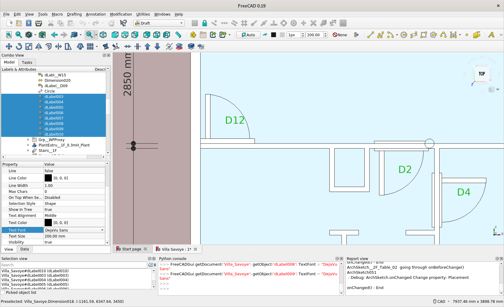
![]() Thanks a buch, i was reading Dlabel as “DOOR label” but now i see the D stands for Draft.
Thanks a buch, i was reading Dlabel as “DOOR label” but now i see the D stands for Draft.
so for “Door Tag”
Ok i gave it a shot and atleast techdraw can see the tag but it’s representation is not right.
OS: Windows 10 (10.0)
Word size of OS: 64-bit
Word size of FreeCAD: 64-bit
Version: 0.19.20943 (Git)
Build type: Release
Branch: master
Hash: ceb23799c76df3ebfa7be4b9fe83bb62de60bc6c
Python version: 3.8.2
Qt version: 5.12.5
Coin version: 4.0.0
OCC version: 7.4.0
Locale: English/Canada (en_CA)
Forgot to answer this question. I have almost never try font - as when I move to Fedora (from Win, quite long time ago), I have never figured out where are those fonts and seem problematic if e.g. using a font in Linux but opening it in Windows… then never pick it up again ![]()
I might try fonts here again.
BTW, when FC font is Null, what fonts would it use ?
On mine it says this "MS Shell Dlg 2
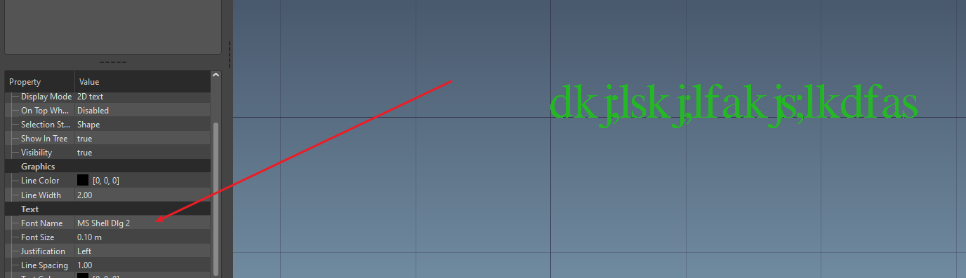
But as you can see when i change the fonts, it doesn’t update with the changes.

Note: “MS Shell Dlg 2” is not actually a single font:
https://docs.microsoft.com/en-us/windows/win32/intl/using-ms-shell-dlg-and-ms-shell-dlg-2
This thread is going really fast and far ![]() hard to follow everything…
hard to follow everything…
Two things:
-
Regarding “working in 2D”. Don’t know about you guys, but I really dislike “working in 2D views” like in Revit. This seems to me a gross way to try to make “old-school” architects feel at ease in a 3D application by “faking” that they are working in their favourite old-school CAD program. It seems to me that modern"pure" 3D apps like FreeCAD or Blender offer a much more convenient and practical 3D space, where it is super easy to mask, disable/enable objects, place yourself in exactly the view you want anywhere in the 3D space, and be able to work efficiently directly in the 3D space. My opinion is that we should free ourselves up from the Revit heritage and mindset, and concentrate in having everything work in all possible manners in the 3D space itself. Specially with @realthunder’s selection improvements, it’s becoming really comfortable to model directly in a 3D view in FreeCAD. That doesn’t mean we can’t offer cool “shortcuts” to clean, 2D views of your model (maybe even with white background and screen widgets like “view limits”), though, but we should always take advantage that it is still the 3D space and not try to go around it.
-
The autocad block idea is cool. We could have some new “Draft Symbol” object, that can, for example:
-
take its shape definition from either FreeCAD shapes, or an SVG file, or a DWG/DXF file (so it could use the zillions of DWG block libraries out there)
-
create dynamically properties for each “mutable” text or attr in it (we already have a way to define those in svg)
-
it needs a way to store the position of each text too (a vector pos for each of them? and also individual color, size, font, etc? maybe then these properties should all become lists…)
-
now string properties are also supported by the expression engine, so it’s really easy to make these texts dynamic and for ex. take a window tag
Are you refering to techdraw here?
I agree with this but still we ha no real ways of handling proper expressive documentation, for example electrical notes, structural notes, design notes, good material tag behaviour etc etc so there is still a need for laying anotations on a 3D flat surface like workplane.
I also share this view.
I’m also up for this.
Can’t wait to see this in action.
On my Fedora 31, it is just ’ ’ when nothing is input - so I have no idea which Font it is using ![]()
thanks @onekk, I really understand a lot more of how the FCStd format works ![]()
Well, that’s good! ![]()
Regarding “working in 2D”. Don’t know about you guys, but I really dislike “working in 2D views” like in Revit. This seems to me a gross way to try to make “old-school” architects feel at ease in a 3D application by “faking” that they are working in their favourite old-school CAD program.
I’m really convinced that it’s not like this. 2d it’s not something old school just because it’s 1D less than 3D.
2D it’s more conceptual. It’s simplified. It’s straightforward. It helps to improve the control of the 3d model. I do not think that It’s something old fashoned. And I do not think that providing a decent 2d experience has anything to do with trying to mimic some other softwares.
And for 2D I do not mean something far from the 3d space, in a different place, or worse, just an output, but the possibility to work with a 2d view INSIDE the 3d space, and in 3d!
But that’s just my opinion. Maybe i’m just living in a Flatland - Wikipedia. ![]()
I call our world Flatland, not because we call it so, but to make its nature clearer to you, my happy readers, who are privileged to live in Space.
For now i’m just okay with a working solution that can get any serious work done. So if it’s 2D fine, if it’s 3D fine, but right now techdraw is not a solution.
I meant changing the font of any darft annotation text or draft dimensions. is that working on your side?
Some more advanced infos, hidden in full view on FCstd document
https://wiki.freecadweb.org/File_Format_FCStd
Maybe this could lead to some advancing.
I’m exeprimenting with squlite3 as an interface to hold many objects, the result seem very good, a test creation of 1000 annotation object and a susquent sql query to retrieve those having a specifical styel associate rougly 300 is almost instant done, the powe of the SQL language could be leveraged on doing complex queries and the single file database produced is easily embeddable in the standard doument file.
plus using json serialization, even tuple could be put in the db field, and maybe even more complex objects, as in the data definition is told that using the type BLOB even binary files such images and so on could be included in the file.
It use the standard python3.x libraries as squlite3 is part of them.
Regards
Carlo D.
Carlo, this is just chinese to me… ![]()
@realthunder, @yorik, is this thing onekk is describing something that make sense to you?
I’m not sure if this is relevant and I do not understand how all this works but the Geopackage format is based on sqlite but has spatial components that may be useful. https://www.geopackage.org/
In QGIS I think it works similarly to what you are trying to do. The file that QGIS uses to store document information is .qgz (zip) file that contains the files that are used for the document. Most importantly a .qgs (xml) file that coordinates all of the other files. Because in GIS these files that are coordinated tend to be stand alone files that live outside of the .qgz file QGIS uses the data from external files such as a geopackage to label features. Often many thousands of features. There is also a .qgd (sqlite) file in the .qgz file that keeps track of labeling overrides that have been made for this particular QGIS document. https://docs.qgis.org/3.10/en/docs/user_manual/appendices/qgis_file_formats.html
Just dreaming here-
I am interested in being able to coordinate more between QGIS and FreeCAD and if the file format was based on a geopackage this may allow for that connection although sqlite might work too.
Have a quick test - it seems it works ![]()


Hello baswein, nice to have you here ![]() I’ve been reading your presentation in community.osarch.org . My compliments for your works, it’s really interesting and inspiring.
I’ve been reading your presentation in community.osarch.org . My compliments for your works, it’s really interesting and inspiring.
Thanks for contributing to the discussion… I think we are collecting a lot of interesting ideas and points of view… ![]()