[Discussion] Drafting 2d annotations for architecture

A big concern to me is how to properly produce 2d documentation of architectural models.

On the Re: DraftSight 2019 no longer free topic we were following up the discussion about some of the limitations of current workflow because we probably just can’t think about annotations the way we are doing it now: FreeCAD probably will always be affected (?) by the problem of not being able to contain many document objects in the same doc.

So being able to handle proper annotations (expecially in arch models) can quickly become problematic.
Think about a model with 1000 object: quite common. If we have 500 lines drawn over it it means we are already at 1500 obj. If we have 2 plans and 2 sections, everyone of them with dimensions, detailing, etc. we could reach quite quickly 3000-4000 objects.

So it’s probably good to invest some time to addreess this future problem now, or in the near future.

Know it’s not so elegant, but I need to ping :

We were thinking about a kind of huge single document object capable of containing many subobjects. Those subobjects could be in my vision lines, text, leaders, labels, dimensions, arc, BSpline, etc.
At the beginning it would be good also to have a test with just lines.
The point with annotations is that we do not really need to have those objects have a shape, so they can be 100% coin and they can be 2d, really just laying on a SectionPlane, so we do not need them to have a Z coordinate.
Probably from the mechanical point of view, such need will never emerge, because you can always provide annotations with techdraw workflow, since you need to mainly dimension single Parts, and less frequently the whole assembly. In Arch workflow instead, it’s mostly a matter of dimensioning the assembly rather than the Parts.
But anyway it would be nice to improve annotations in the 3d view. And probably Draft is the good candidate (We already have there Text Dimension and Label objects that are 100% coin).

Here you have a reference to a post in which I sketched a potential workflow with Arch views and annotations.

Can we put a bit of thought in this direction?
@realthunder, do you think it could be feasible to have a huge document object containing single simple coin entities or group of them (like dimensions and polylines)? Be able to select them individually and give everyone of them a proper visual style (color and linestyle)?
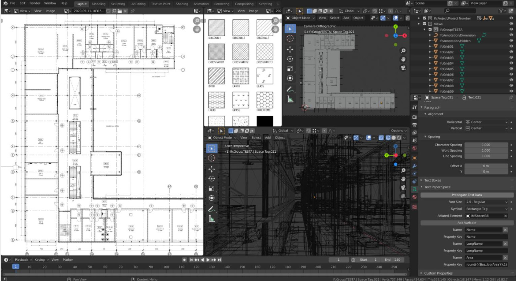
It would be a bit like having a 2d LibreCAD sheet into FreeCAD 3d View… (or imagine importing a huge drafting 2d sheet and be able to show as a single object, but divided with layers :question: )

Few ideas and really confused, i’d like to know what do everyone think about that, and if it’s just me that is really concerned about this point for the future of architectural workflow. :slight_smile:

Edit: I feel I have to apologize for overusing your help @realthunder in the last times … :blush:

Before @Realthundar make response :slight_smile: … there seems to be real needs for more development in this direction. I have only tried some simple dimensioning and annotation e.g. in the Villa Savoye model, it is far from the ease and robustness in say AutoCAD R12.

@Regis did quite several models with 2d objects and dawings …

Hello Carlopav, this is a great initiave, we are already somewhat familiar with the general potential of the 3D modeling aspect of Freecad, however what is heavily underlooked is it’s 2D drafting and annotation potential for serious documentation. And like you’ve pointed out the current workflow doesn’t work. Freecad initially was meant to be a promissing solution for BIM and documenation, but right now it fails on documentation and that perhaps where i’m very very very dissappointed by freecad and always feel the need to revert to commercial applications. I’m certain this is the feeling of other proffessionals when ever they take a look at freecad for the first time, the question is can i do serious with it, and when they see they can’t do serious work, they run away like a gazelle running away from a leopard.

First of all, freecad text, i’m not sure what’s happening under the hood, but on my system i’m unable to change the font for a font I wish. This used to be a major issue when i worked on linux, and now that i’m on windows i find the same issue. I’ve looked through all possible documentation on the forum addressing this issue and all of them did not work for me. So it’s just painful that I imagine every user having this issue when it is supposed to work right out of the box intuitively. So perhaps we can think of a different way even for text fonts in freecad?

I 100% agree here, everytime i want to get serious with work, i end up spending hours and hours just trying to fix what was already working before and looking for different ways to address what isn’t optimal, in this kind of option Freecad is not useful, freecad is not efficient, freecad is not measuring up to the ‘least’ standards when it comes to documentation. So i agree with you that serious input need to be given to this area of freecad.

This has been my main problem ever since i started with freecad.

Couldn’t agree more.

This is a good idea, i’m sure there is some hidden results that can come out of this.

This is also what i think is essential, improving annotation in the 3D view, WHY? because

  1. currently doing the annotations in techdraw is not up to the architectural mindset,
  2. Techdraw can start to drag Freecad and make it super slow, everty time it has to generate a change made in the intial model, and yes even if you toggle off the generate, and have to come and generate the changes do it manually in techdraw, it is still terribly slow when the projects gains in maturity and size.
  3. Techdraw is a flat 2D generating inskscape vector stuffs, in most programs like revit you are still able to edit the model in the sheets views, which is hightly useful and efficient. So working directly in 3D allows for such possibility of editing what needs to be edited in 3D and see the changes real time being updated and tweaked using the general move, scale, mirror… etc etc tools that are areadly available + less time to generate the 3d.

I still think there is potential in techdraw, but how i see techdraw is more as a placement space, where there are things like align the drawings positioned, importing templates made from inscape (which is great because once the template is created it’s set and so all kinds of creative templates can be made in inkscape). I see tech draw more like Scribus, where once you have everything nicely created you can come and place them nicely and export everything at once, but everything of good and changes must happen in 3D view. I also like tecdraw because i can export drawings and they will appear in inkscape with transparency on them. Currently if we were to apply the picture snapping mode to take pictures of the scaled view drawing in freecad, it doesn’t have that vector ability to take a picture and apply clean proper vector transparency on the model, it does scalar transparency so when you zoom on it, the picture is pixelized. Not great at all.

Currently the way I use Techdraw is to scale my drawings to the size i want because i’m not sure how it will fit on paper at a certain scale. (one way to get around that is to have a scale view directly in 3D where when the scale is applied, some view camera created in 3D view zooms in to the scale and what ever fits in that box allows us to determine in which scale the drawing or object is in.

I also played a little bit with Qcad and Librecad to understand the possibily of doing sheet editing on there after i export the dxf, I think if freecad just had 1/5th of Librecad text and annotation possibilities, it would be a major step forward. Literally no kidding. Right now the workflow is not so great because

  1. you must learn librecad when you already took the time to learn freecad, this might not make it so interesting for people (and especially me) to always have an extra stuffs to learn just for the sake of productivity when we need to design and focus on acheiving the design we need,
  2. No real time instant updates as when the drawing changes as it is often in the architecture world, changes are made on the minute basis, so if every time you need to go and update something in 2D, then it’s pattetically painful and less attractive. We will never stand a chance of convicing someone to jump on freecad when they see the ease of commercial softs when it comes to documentation (no to mention that the 3D modeling it self is not rocket science as it’s still in developments i.e still needing smooth hatches, smooth textures, smooth materialities etc etc.

So in summary here is what my tinkering experiences suggests if it is possible from the Code point of view

  1. Everything Annotation and dimension must happen in 3D View directly
  2. The Section/Elevation should be enhanced further
    As for wether everything must be layed on it or not I think that’s relative, there are advantages and disadvantages, but in general having a type of sheet like/page that is position exactly where the cut occurs where it can host every annotation created (and this page can be now hosted to move with the section, that would be great.
  3. The Section/Elevation should be flexible, i.e we should be able to drag the edges and size it up as we need it. This is especially useful for stuffs like interior elevation plans or ‘section boxes’ like in revit or ‘marquee selection section’ like in archicad for viewing a small section part of a project.
  4. An ability to scale a view, I like the way blender does it in that it has a camera and everything concerning that view happens in that camera, so if you scale a view in the camera, it doesn’t affect the main view. Why do we need scaled view, because it is useful to know what size we are dealing with and have accurate exports of drawings, let’s say in inkscape, or dxf for further enchancement in another projects.
  5. An ability to have transparency of the objects viewed by the camera, aswell as have the ability to apply background color to that view if desired.
  6. The camera can actually be where the Sheet is placed and sized, so it is somewhat invisible or semi transparent while we are working in 3d view and can see what happening when we are placing drawings views and sections on it. etc etc.


    So that’s my 2 cent suggestions, I hope i’m not asking for anything impossible.

there are also some development by @moult to provide blender with documentation capabilities

https://blenderbim.org/features.html
https://www.youtube.com/watch?v=CPGFC566Lmc&list=PLgAKO-tNTLzZOCpCthvrnw877S893nF-b

And his works with documenting in blender
Snipaste_2020-05-13_12-57-38.png
Snipaste_2020-05-13_12-57-13.png
Snipaste_2020-05-13_12-56-35.png

100% agree with everything you wrote regis. This is also my feeling. I think what we need to improve this field is 90% already present in actual Draft and Arch code (yorik effort in this 10 years is great and is what brought everyone of us here), we just have to adapt it to be more efficient! If we can do so… well… FreeCAD Arch will just rock baby!!!

Having many object in a document could be dangerous, maybe a new format is needed for complex objects.

Some other piece of software have found a solution, maybe not elegant, but easily implementable.

The document is simply a compressed directory, expanded at opening, put in a temporary directory, modified there and recompressed at saving.

In this way there could be a “traditional” FCstd file that contains all the 3D work and several other files containing the “special features” like drawings and other.

Simply use another extension, to tell FreeCAD that this document use “the complex format”.

LibreOffice for example use a similar approach you could modify the document name changing the od… suffix with zip and unzip into a directory.

In this manner you could insert many objects, even some databases, images and so on and it appear a sigle document.

Cheap and dirty, end even “serviceable” in case of problems, you could add whatever you want, even backward compatible, if the new features reside in a separate file the standard FCstd file will ever be readable if no newer feature are introduced.

Just a thinking.

Regards

Carlo D.

Good account of FreeCAD capabilities and shortcoming :slight_smile:

Have you joined the OSArch.org ? There workflows possibilities should be discussed.

I intend to have another deeper look at libreCAD, Inkscape to do documentation with FreeCAD. It seems you find this workflow not very efficient right?

Hopefully with more capable hands like @Carlopav to help @Yorik’s development, there will be much faster development and improvement in several critical aspects peoples identify and debug.

Any time to help developing Arch / BIM in these aspects? :slight_smile:

:laughing: :laughing: :laughing: :laughing: I like your galvinising speech, that’s the spirit of a leader

The problems that you mention seem to be about scalability, but they seem to be similar to what mechanical engineers face with big assemblies. And this is the reason App Link was developed; it is supposed to help with this problem of many objects and reusable components.

How much have you tried App Link? I feel the natural way of approaching this is to really start breaking down a single project into subfiles, all tied together by App Links. Essentially, you can have many objects in one document, but link to them in another document.

The same problem is discussed in TechDraw. TechDraw is apparently quite slow with big mechanical models due to the underlying hidden line removal algorithm that comes from OCCT. So, a partial solution could be to place the drawing in a complete different file, and import the 3D geometry through App Links.

This sounds like a good idea, it also sounds like the BIM workbench which is sperate from everything else, i’ll leave the code experts to comment on this approach but it sounds interesting.

I agree with @Vox
I tried to create drawings of a model in external files using App Link.

Here the thread…

https://forum.freecadweb.org/viewtopic.php?f=35&t=41973

The examples were very simple, and @Wandererfan solved some problems about external file…

I didn’t try large model model yet…

Some commercial softwares create external files to lighten the 3D model…

App Link also works with the Shape2DView function…
The user can create the 2D views in the model and insert annotations, dimensions in the external file…

As for now i’m a side observer of the discussion as I see it’s mainly highly experienced programmers engaging in and i don’t want to look like a poor ignorant that I am when it comes to programming stuffs. However moult did me a very basic tutorial demonstration and did find it very interesting aswell, and very promissing.
According to me, we should take what is good about librecad and implement in Freecad, and really look at a combination of Freecad and Inkscape for documentation because what Freecad lacks, Inkscape has it all, and what Inkscape lacks freecad has some of it, so it’s a good blend. Currently I see inscape more as the place to prepare templates, nice presentation templates, things that can be reused many times once they are done once. So documentation must happen in freecad because it reduces the amount of times someone was make a change in the model, then export, then re-document in inskcape, that will very quickly become inneficient and unproductive, the more we can make freecad less dependent on inkscape the better we shall be, but the more we can provide a initial template setup in inkscape for freecad then i think this is best, for example we can make Hatches in inskape so easily and then import them in freecad, this process doesn’t need to involve going back and forth, once it’s done in inkscape it’s done, and for presentation, if you imagine big presentation boards can be prepared in inkscape with their colors and effects and then saved, and pull it in freecad and just drop the plan ontop of it.
Ah also the naming of sheets, like the names, sheet numbers, revisions, etc etc, that must be carefully observed because we need a working template that addresses it all at once and is flexible to many changes at onces, currently the techdraw way of doing it and rellying in inkscape doesn’t appear as efficient and most often a newby can’t modify and create his own so easily. I i don’t want to use the preset templates and need to create my own, i’ll quickly realize that i’m stranded, so that defies the mindset behind open source in terms of flexibility in customization.
So that’s my 2 cent opinion on that.

I’m sorry I started this conversation with probably too little knowledge about this topic, and most of all with absolutely no idea aboutn the direction to go to solve it… so thanks everyone for the ideas, it’s nice to see i’m in good company :slight_smile:

:blush: sorry for giving this impression, never aimed to this in my life and i will not start now! :unamused:
(saw Moult work and i find it really interesting, but before arriving to IFC export of annotations I believe we have to concentrate in FC first)
by the way, as @paullee suggested, would be nice to see you around in https://community.osarch.org/

Thx Carlo, This is a really interesting input. I really lack in understanding how this could work indeed. I guess FCStd format is already a kind of compressed folder, but I’m not sure about that… So you mean we could “include” a “DXF or wathever draft” inside FCStd and be able to display it. This is somehow similar to the idea of having a big object that could contain all the annotations of an architectural section for example?


I’ve been thinking about that quite a lot in the last year. I my experience the object limit is easily reachable within one single architectural draft (at least in my experience). Imagine a floor plan of a small residential building, where you want to draft the sewage system or the garden, or a site plan, or an interior plan where you have custom furniture… I start to have this problems if i draft just one single flat sometimes…

Hi Marco, thx for the link, i hadn’t see it before.
Well… yes, I was thinking to more complex designs, expecially with many annotations. Definitely this tecnique can be used to lighten the model a lot as @vocx pointed out. And it’s what i usually use when i’m dealing with complex buildings: one floor per file. The issue pointed out here was just: if we have to economize the objects in FC because they can’t be infinite, why a super stupid 2d line should consume one object slot?

Nothing wrong brother Carlo, we are all of light hearted spirits so we can indulge on some harmless tease.

I will join. Just my brain is also all over the place aswell so sometimes hard for me to be consistent with what i follow. But i’ll check it out.
I’m currently reviewing your progress on this post car I think you have some interesting developments going on here
https://forum.freecadweb.org/viewtopic.php?f=23&t=44965&start=70

I think we shall aim at being able to handle 10K+ objects per session. However, for the drafting use case you described here, I think it is best to not expose geometries as individual objects. Why not follow the Sketcher WB approach, once double click the object, you can then expose individual edges for further editing.

I don’t know the format of Fcstd file. I have asked but no one has answered me.

But if you create a libreoffice, openoffice file, you will see that if you change the extension in zip you could open it with an archive tools or simply unzip it and you will find a directory tree with many file:
libreoffice.png
I suscpect that most of the machinery is already in FreeCAD, maybe chosing a compression alghorithm more efficient than zip will be better, but it is not very crucial.

In this way a document could contain almost everything.

Images, text file, even spreadsheet and database file, or even his own set of Macro, or even a whole workbench.

You could imagine even a scenery where you put into this file the machinery needed to manage a completely different approach.

incorporating annotations, as Yorick say about a csv file, will be more easier, the “FCnew” file will contain maybe three file:

  • document.FCstd
  • ann_styles.csv
  • content.xml

Only a rough example, in content.xml will be the glue of whole document, maybe a description of the content of the file, some comments and so on.

For a more complex approach:

  • document.FCstd
  • ann_styles.csv
  • content.xml
  • document.dxf

To not reinvent the wheel maybe if the machinery is present, or a decent 2D cad library could be found, the entire Drawing workbench could be managed by a completely different library in DXF format, that is a somewhat solid standard.

Images, material texture and whatever you could imagine could be put in place, if not needed or not supported it will be simply ignored by the program that open it.

Simply in FreeCAD at the start we have to add a filter for the file name, a decompression code into a temporary directory and simply load the document.FCstd.

an ipotetical skeleton of the content.xml would be:

<?xml version="1.0" encoding="UTF-8"?>
<freecad:document>
<version num=2020 />
<main>
./document.FCstd
</main>
<styles>
ann_styles.csv
</styles>
<drawings>
<page num=1>
page1.dxf
<\page>
<page num=2>
page2.dxf
<\page>
<drawings>
</freecad:document>

Obviously for each task and workbench maybe a different file will be created, so if you have to modify the 3D part you have only to load the 3D part and the drawings or the textures are not loaded.

Obviously it has to be discussed by the main developer as it is better to make some discussion on some aspects.

But the power of this approach I think could boost FreeCAD development, as when someone will add a new workbench simply anew file that contains the relevant information for this workbench is added.

Think of a document with a some 3D objects and all the technical drawings, maybe even a pdf file with the manual with the specifications and so on.

There were discussion on how to implement the IFC translation in FreeCAD, simply it will be not necessary, the IFC file is simply a part of the new container and only the translation part will occur.

Suppose that FreeCAD version 2020 will manage only 3 or 4 construct of the iIFC part, and maybe version 2023 will manage 10 cnostruct, the 3 years old file is preserving the original IFC file, so the 2023 version could manage and visualize, and maybe modify more information than 2020 version, but the carefully created “version 2020” “FCnew” file will be used without modification.

Only my two cents

Regards

Carlo D.

FreeCAD is about the same. The FCStd file is just a zip archive, you can unzip it with any standard zipper. But you can’t re-zip it with standard tools, because there is requirement on file ordering. There is script for doing that. On the other hand, you can try with my fork, which allows you to save to and restore directly from directory without compression. It is meant to allow use of external version control software. The content of the directory is self-explanatory.

OK all the machinery is in place, changes are more easy.

I gave a quick view at the file, and it seems that it is not a big problem to extend the format to include a more articulated directory tree, from what you know there is some documentation about the file format around?

Regards

Carlo D.

Not that I know of. Adding new content for C++ is pretty straightforward. Not sure about Python, though. Yorik must know about it.