So I plunked money down and bought a small cnc for retirement … a onefinity to be precise.
One of the operations I would like to do with it is inlay work … basically cutting out male/female parts and joining them up ( here is a youtube: https://www.youtube.com/watch?v=WYnO8kSHQ1c )
Is this something that FreeCad/Path can accomplish with relative ease?
A few weeks ago sliptonic added the v-carve op, which should allow you to create the negative. Creating the positive is not possible straight out of the box. You could probably establish it by creating two models, one for v-carving the inlay positive and one for milling away the flat areas. The gap is that the v-carve op today does not bottom out at a certain depth.
mlampert is too modest. He did all the hard work on that operation and we both know it.
But he’s right about the state of things. Most of the pieces that you need are there but the workflow isn’t going to be as integrated and polished as the video shows. For example I just started putting content into the Vcarve wiki page yesterday and it isn’t finished so documentation is going to be skinny.
Still, I’m happy to work with you and help resolve bugs as you hit them. This kind of marquetry is one-use case that I’ve had in mind for years. I’d especially like to see a workflow that does 3+ color inlays.
We are glad you joined us. As you ask about inlays and FreeCAD, the answer is yes. However, for your benefit, the “easy” qualifier is subjective based on one’s knowledge and skill with FreeCAD, and one’s ability to modify FreeCAD’s code to extend functionality. Also, “easy” depends on the complexity of the product you wish to produce. The example you provided via the video is very detailed (containing lots of small, acute angles and tight curves). This type of product would likely require the new VCarve operation mentioned above by Sliptonic and MLampert (two well seasoned and senior contributors to Path WB). However, other less complex and common inlays like the simple two presented in the first minute or so of this video, Using ShapeOko 2 and Easel CNC Router for Inlay, have a distinct characteristic that none of the curves or corners have a radius smaller than that of the endmill used to cut the male and female pieces.
I believe that the simple, less complex inlays could be done using a combination of the Profile and Pocket operations with a small diameter endmill, without too much work in FreeCAD’s Path WB, as it stands.
The more complex inlays will require some additional thought and creative use of existing Path WB operations (likely to include the new VCarve), and perhaps some additional modifications to the code to address the VCarve depth issue you all reference above.
You are sure to find a great group of helpful, capable professionals and hobbyists here in the forum who will help as they can. With your assistance and feedback as you take this inlay journey, there might even be an inlay toolset or operation come to be within the Path WB (or a prototype macro) sooner than later.
I’ve had good inlay results using the software in this video: https://www.youtube.com/watch?v=8ty7ITWadv8
success depends on having a v-bit that comes to a very true point or alternatively doing a small trig calculation for a tool with any amount of ‘flat’ on the tip.
My advice is to try the proven method using F-engrave unless you’re willing to spend $600(?) for Vectric. Trying to do this in FreeCad before getting a feel for and understanding of the inlay process is going to lead to frustration. As mentioned by Russ4262 using straight bits for inlays has limitations and my guess is the fit-up is fussier.
Sorry for the delayed response, daughter is in the ICU… not covid but similar, she is coming off a vent, so not out of the woods …but she can see the edge of the woods.
A bit about me, I am a Mech Engrng who writes code for other engineers to use. I use stuff like C++/Python/Git/Jenkins/UGOpen/Qt/NURBS …so raw capability I am Ok with. ( My wife is an EE but will be in our shop too… ok she just gave up on freeCad she is a 2D drafting person not a modeling person… it was not pretty chuckle)
I believe I am convinced freeCad / path is worth the the time investment… it has good bones
My machine is not scheduled for delivery until Jan/Feb … they have a 2-3 month back log.
So my timeframe is Nov-Jan learn to model in FreeCad. Cut first chips March or so (depending on retirement date)… move into V-Carve then into inlay work.
Thanks for the response … they were a big factor in convincing me.
The vcarve/female toolpath for an image like this looks like it may work. This is my first attempt with this op so it is what it is. Creating the male/prismatic portion is beyond my skills and I’m too green to even guess how that could be done. Looking forward to seeing what direction this takes and thanks for the tool paths.
ps if the images post huge I’ll know better next time.
Your female part looks good. Do you have the FreeCAD file to share with the progress in the images?
I am thinking:
Make two copies (one to contain the male geometry, the other to trim the male geometry to thickness) of the base block containing the female, without the female geometry.
Set one copy on top of the existing female and lower to necessary depth (overlap) to catch all of female gemetry.
Use the female as the tool to cut the male - Part Cut operation.
Use the second copy on top of the male geometry now created, and lower down on male geometry in an overlapping fashion to set the finished thickness of the male geometry.
Use the top copy as the tool to cut the male geometry - Part Cut operation.
Use the Profile tool with the same tool bit, set to no offset (so the tip of the bit travels on the outline of each raised male geometry section.
Use a PocketShape operation to clear excess material around the revealed male geometry.
Apply boundary dressup to the PocketShape path above to limit time spent on the CNC clearing material when you probably plan to cut out the raw male geometry, leaving a buffer around it as a whole. The boundary dressup should be roughly the shape you wish to cut out the raw male geometry before mating with the female. (This step can also be achieved by cutting the male-containing solid with another boundary solid in the model-refinement steps above.)
Apply a MillFace operation to take the male geometry down to proper thickness.
** Maybe reorder the last two steps above to achieve a better finish on the upper edges of the male geometry.
These are just my thoughts. I have not made an inlay before, but am familiar with the concept, and some of the code here in Path WB. I could be completely incorrect with the above procedure for continuing the inlay process you have begun.
Thanks for the detailed response Russell, I’m digesting it slowly. I’m really new to some of these concepts .
My problem may have been over thinking the problem. The same svg used for the vcarve path can be used for the prismatic/male cut with an engrave path and clearing op. I still struggle a bit with defining the stock and cut depths but it’s progress ??
Camotics is being used for the simulation.
hello CandL
I hope today finds everything well with you and yours and apologies for stepping all over your thread.
This isn’t my finest work (skills are a bit rusty) but it is proof of concept. The inlay is 2.5" x 2".
Tool paths used were v-carve, profile, pocket and adaptive clearing.
For a proof of concept,thats nicely done.I am watching this thread to see what is being accomplished and may feel tempted to venture into my chilly workshop if I can generate some code.Still very much a novice with Freecad but it seems to get better every week.
Glad you were able to get it to work, I am having issues trying to get the female part done with the Vcarve strategy. I have a simple Christmas tree shape.
I took it into Inkscape and made a path object then imported it into FreeCAD, went into the Draft workbench used a combination of up and down conversions to get a face, so far so good.
I create the job and create the Vcarve use the face as the object and it computes a path that is sharpening the points but does not trace the edge all the way round.
Any thoughts on what I might be doing wrong? - I have created inlays with Fusion 360 and F-Engrave in the past and wanted to do the same in FreeCAD but I am not able to get female part to look right.
OS: Windows 10 (10.0)
Word size of OS: 64-bit
Word size of FreeCAD: 64-bit
Version: 0.19.23463 (Git)
Build type: Release
Branch: master
Hash: adc6db8f32c17e9f67cb82aa7962d1e42ce061c6
Python version: 3.8.6
Qt version: 5.12.5
Coin version: 4.0.0
OCC version: 7.4.0
Locale: English/United States (en_US)
I suspect you’re trying to do something that we just can’t do yet. Remember, this is a v-carve operation, not an inlay operation. It calculates a voronoi diagram to try to find a midline through a polygon. So the calculated toolpath is going to try to run the V-shaped cutter down the middle of the tree and down the middle of each ‘branch’. This is almost certainly not what you want.
For a true inlay, you need to cut the ‘pocket’. So you want to profile the inside shape with a v-cutter to give a slanted wall. You then want to clean out any acute angle points by raising the v-bit like a v-carve would. For the inlay piece, you’d do something similar but on the ‘outside’
If your inlay pocket and shape don’t have any angles that a cylindrical cutter can’t reach, you might be able to do this with current tools but not using vcarve at all. But you’d have to do some manual figuring.
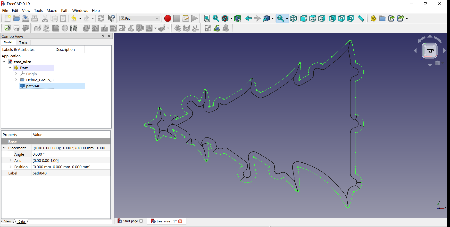
I have a macro(very, very slow) that is producing edges for this. I recently completed an alpha version of a sorting algorithm to assemble the edges in cutting order.
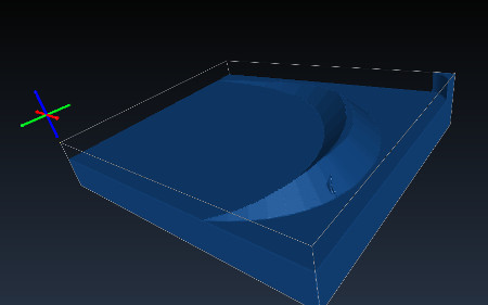
The first attached image is a test wire. The image contains a face, a green/red v-carve path created with recent Path WB, and a black edge set produced with the macro I am developing. Both the v-carve and macro are set to same depth, but v-carve has an error on depth, apart from failing to produce an inlay path in this case. (I shared this image and some info with MLampert on Gitter a few days back.)
The macro can return the mid-line if need be, but the main purpose is for profiling with a v-bit. I might extend usage to profile with other bit shapes in the future. The tool shape used in each is the same. As you mentioned above, you can see a small area in the low spot that would need to be cleared with a regular Pocket op and appropriate bit.
For an inlay on this shape, the v-carve op is not usable; although, the v-carve op is usable on certain use cases. The macro produces the correct paths(edges to be converted to paths) for this shape.
The last two images just illustrate another test case with my macro. It is looking good! The macro is not finished. I hope to have it return the interior regions as faces that need regular clearing - sort of a rest milling return data. I am working to finish my 12x24 storage building so I can again gain access to my CNC router and test some of the code on real material.


