Have been experimented this for a while, and with @Realthunder’s guidance, adding this to Arch Windows and their Links
[EDIT 2]
Support for ArchEquipment are added in post below
[EDIT] Concept of Intuitive Placement in Arch : Placement of Windows/Doors should be like -
'placing at this end of wall / corner of the room;
by an offset of x mm, at y mm height Along the wall (edge) of the room’
and it stick with this position no matter how the layout of the room / wall segment is edited subsequently.
(and probably similarly for other Arch Objects - e.g. a WaterCloset along that wall, offsetting from end of wall by say 800mm)
Discussion of Link support here
Discussion about Links of Window not creating hole here
Add a new Window/Door by clicking the Window Button
Made sure no Draft Snap is effective
Just input 0,0,0 in the Global x,y,z, and [Enter] to create the Window/Door
Find Hosts in Windows ComboView Data Tab
Click […] and find a Wall object would attach to and create opening
The Window placed itself along the starting end of 1st Wall Segment
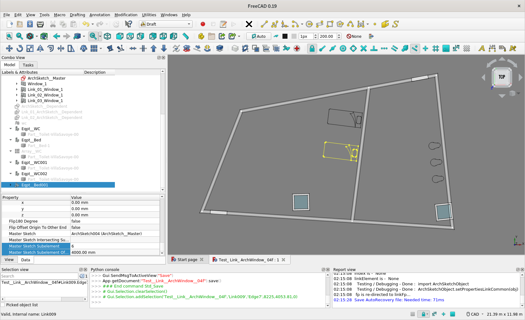
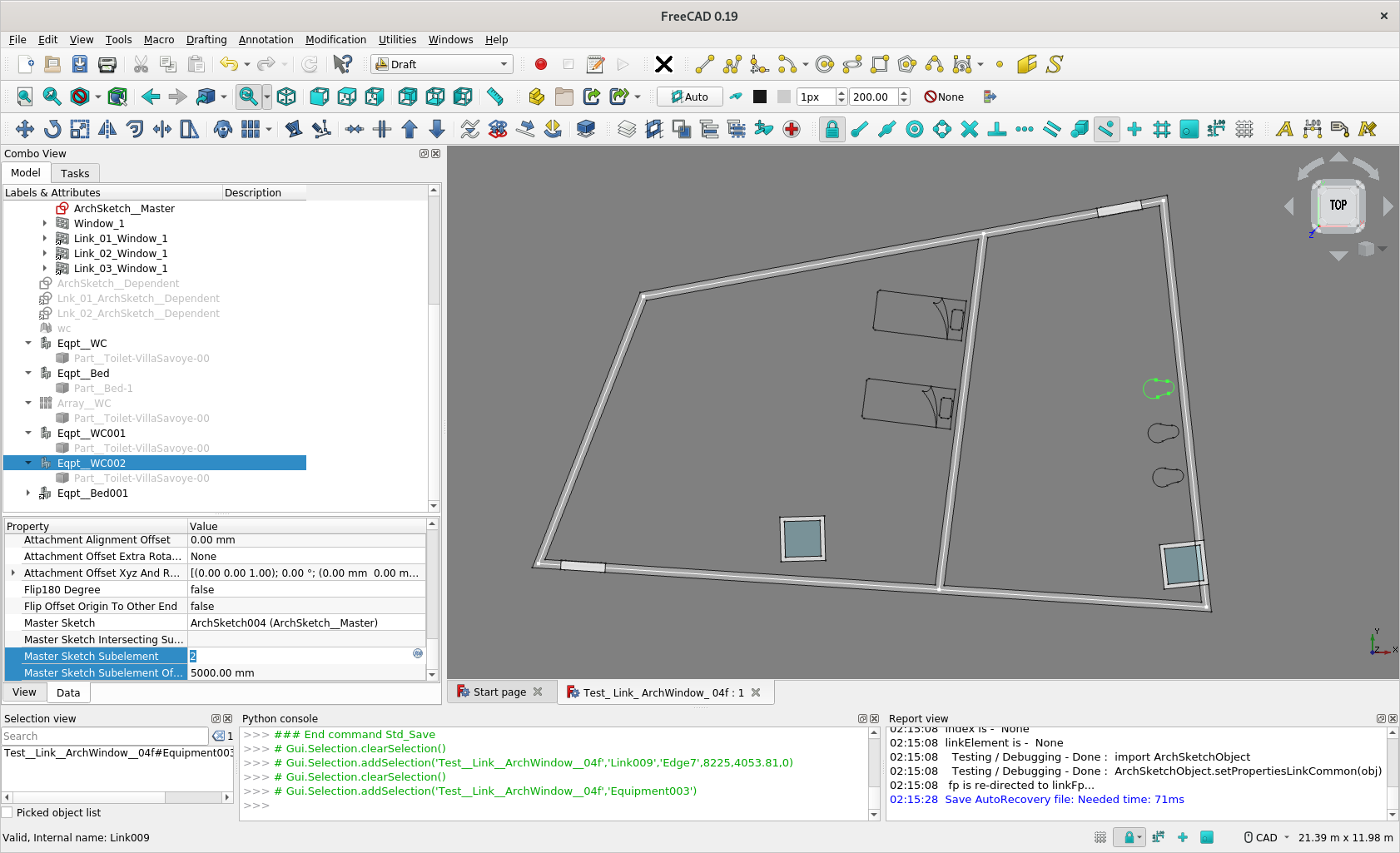
Enter [1] [2] .. in Master Sketch Subelement to make it slign to nth Wall Segment
Enter the offset distance from the end in Master Sketch Subelement Offset
Enter the height of Window in position-z in Attachment Offset Xyz and Rotation
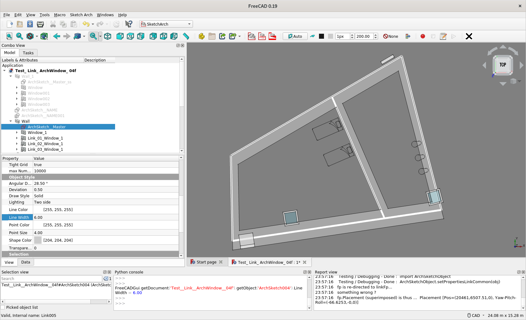
Edit the Wall base Sketch, the Wall shape changes, so do the positions of the Windows (Links of Windows)
Work In Progress / Desirable Workflow
Renaming Attributes e.g. Master Sketch Subelement to probably Edge or Segment, Attach To Objects - Hosts, etc.
Currently the underlying Sketch of Window needs to be at 0,0,0 and upright to make this works
So as highlighted in about pint 2 and 3, do not use snap to a wall. If one move cursor to a Wall with Snap on, the underlying Sketch of Window would align with the Wall face, and the placement would not be correct.
Hope the GUI can be modified to make it compatible
I have experimented a bit with the files in your first post. And it certainly works as you have described. And in cases where users want to keep windows connected to sketch based walls it would be a time-saver. It is difficult to achieve this manually as we both know from past attempts.
I do have some doubts regarding your FreeCAD_SketchArch add-on. To base walls with different widths on the same sketch can be a useful feature. But when entering the more detailed planning stages, in most cases, different materials will have to be applied to wall segments with different widths. As I understand things your add-on does not support this.
The whole intent is to make design development more intuitive and automatic, intuitive as an ordinary people would think of so it would be easier to use and change hopefully. So if you have any idea how those parameters, or GUI tools should be, do suggest.
Currently SketchArch add-on support different width and align for each edge / wall segment. Indeed, it is an intent to add material support also.
‘Short-term’ Target
Current target is to make making preliminary sketch layout more intuitive and easier to modify -
By leverage Sketch inherent capabilities e.g. in dimensional control
Earlier with different width and align for each wall segment
So have a preliminary Sketch Layout good for study purpose
‘Long-term’ Target ?
Then, maybe Materials - maybe 2 ArchWalls on 1 ArchSketch, so each of the Wall ‘output’ Wall Segments of different materials … ?
Indeed, I use the whole add-on on the Villa Savoye model, with some walls in different colour but not developing the above concept yet. Can achieve this by Sketch Link to External Geometry - a series of ‘Dependent’ Sketches linked to a ‘Master’ (Arch)Sketch - though it is not my workflow.
I find I indicated different Wall Joint / Junction geometrical shape in the Github
It’s great to see you update the window/door placement. As requested here ar some suggestions.
Make placement more intuitive. Revit shows temporary dimensions while drawing anything. You can also edit this temporary dimension so it keeps a certain distance while placing. You can also make it centered by click EQ (equal). See: https://www.youtube.com/watch?v=Ehh7vxOBofA
Make window stretchable after/during placement. See this GIF form OSArch community:
In general I really like this UX proposal. Also the capability to select the type of frame is nice.
Can the window/door cut multiple walls draw next to each other? In my country it’s normal to draw the construction wall separately from the architecture wall (isolation, air gap and brick layer). So it can be exported separately and replaced by the modified walls drawn by the construction calculation department. When placing a wall normally it would only cut the host wall. Revit has this nice option to join walls so the program know it has to cut both walls.
There are a few options, suggesting one as follows -
Opening in Wall Layers
Windows has a host option in FreeCAD
Select the Wall you want to punch a hole in the attribute, you get a hole when the Window placement is along the wall
You can Select a numbers of Walls you want to punch a hole in this attribute, and you get same hole
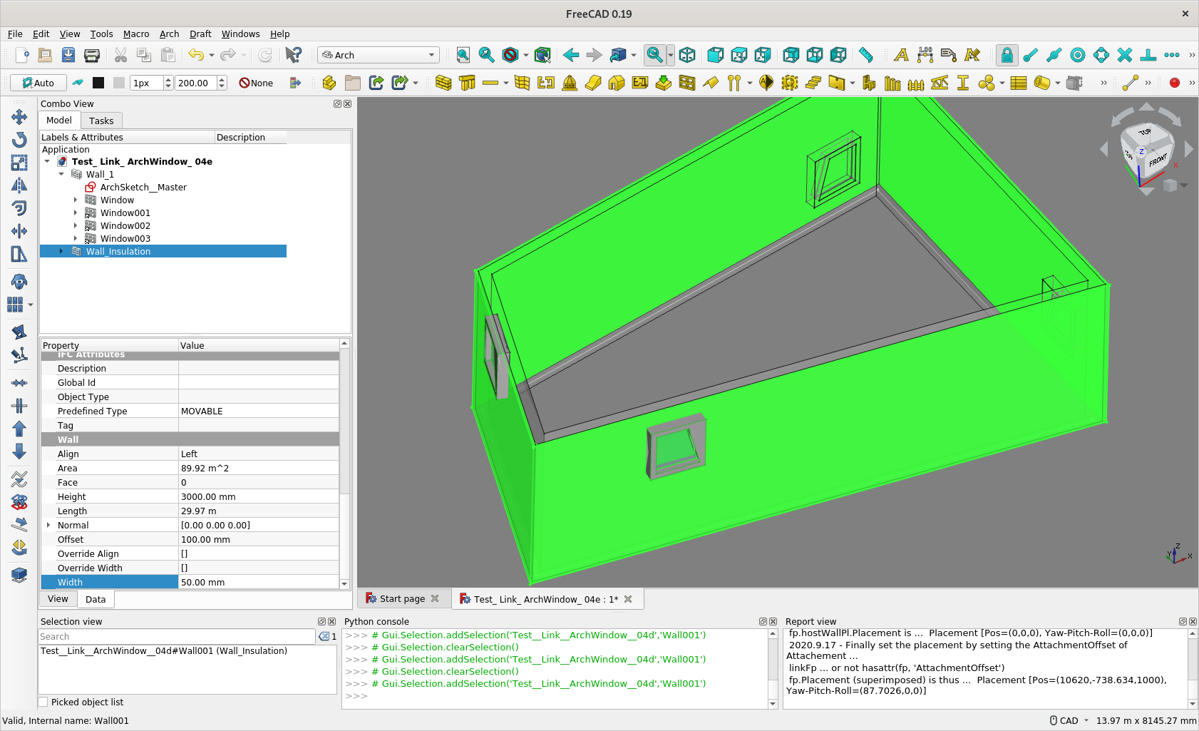
Wall Layers
You can build a numbers of Wall based on same Base (Draft Wire, Sketch e.g.)
By setting different Offset and Width in these Walls, you get Wall Layers
See ScreenCaptures and Model file attached.
These looks great Currently I am more focused on what attributes / concept of placement is more intuitive and easier for designers, see if you have any more observation. Placement at Middle of Wall is one good feature to adopt.
As for the GUI thing, being a python beginner, I am currently far from able to implement these (as 'qualified in my posts ), hope someone want to implement these. You can code BTW ?
Thanks for the wall layer workflow, I will try it later today.
As of placement of window I think Archicad does a great job, see example here: https://www.youtube.com/watch?v=pqL74xIY5pA around 0:42 After selecting the door, and setup of the style/dimensions, they place the door. A thick line shows the placement side, outside or inside of the wall. You see those arrow indicating that you can mirror the window. When the window is places you can change the opening reference depth, this can also be a negative value. Also importend for placing is the insertion point, left/middel/right. Most programs have an icon to select placement point before you acuale place the window/door.
Whilst I am cleaning up the code, I am trying to add this Automatic Placement Support to e.g.
Arch Equipment
Draft Array …
The beds / toilets, Arch Equitment, are now told to ‘attach to particular wall/sketch segment’ at a ’ x distance from the edge of wall/sketch segment’. So you have the semantic meaning for disposition of the Equipment which automatically follow the layout.
Hi @paullee,
I find your approach very interesting
Time ago I experimented designing a parametric floor plan by using normal sketches … but ran into a lot of problems
Different sketches had to be used for walls with different widths
Sketches had to be linked to existing wall edges using external geometries
Installed windows and doors were not adapted to the changed floor plan geometries
This approach was very vulnerable to the topological naming problem, especially if sketches were deleted or changed afterwards. (I was able to reduce this problem considerably by using @realthunder’s LinkStage3-branch)
All these problems seems to be addressed by your solution so let me encourage you to keep going on.
BTW using your workbench I noticed a strange behavior .. maybe it’s just me who owns something wrong.
After creating a wall from an ArchSketch I can flip a wall segment by using the command “EditWallAllign” just like I would expect it to work.
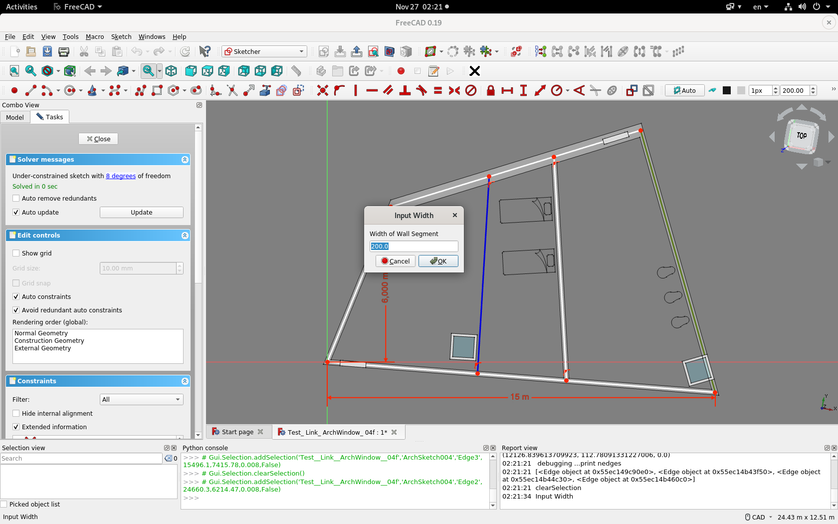
But afterwards, if I try to edit a width of a wall segment using the command “EditWallWidth” and selecting a specific wall segment, first the wall alignment flips and then several input dialogs are sequentially opened. I would only expect one dialog asking me to modify the respective wall segment width (maybe having the possibility to specify unit dimensions?) without flip action.
Aborting the command and re-executing it again makes it worse. Now even more dialogs will open.
Here is a link to a short video to better explain what I mean: https://www.dropbox.com/s/8hsp2xsgiirpfml/ArchSketch.gif?dl=0
Thank you very much for your efforts @balrobs
My system infos:
OS: Ubuntu 20.04.1 LTS (ubuntu:GNOME/ubuntu)
Word size of OS: 64-bit
Word size of FreeCAD: 64-bit
Version: 0.19.
Build type: Release
Branch: unknown
Hash: f9104f5884036864d238c4fcdc7d911c5d9bde0e
Python version: 3.8.5
Qt version: 5.12.8
Coin version: 4.0.0
OCC version: 7.3.0
Locale: English/United States (en_US)
I am not trained as a programmer and am only a python beginner (reiterated ) unfortunately, there are lot of things I do not know how to do. I can only make the command ends properly by pressing [ESC] and there is only a note in the Report View. Maybe before someone can help how to make the command end properly by closing the tasks panel, I should add a dialog box to tell how to end these two commands
So, in the meantime, remember to press [ESC] key to end - even myself forget to do so lots of time.
Then, thanks for testing the experimental WB I have explained somewhere about the vision and current implementation and the development direction as an architect. However, the features being experimented had not been fully exposed in the ArchSketch in github for some reasons and limited time. The capabilities to have different Align and Width are ‘partially’ supported on ordinary Sketch currently (and ArchSketch is in fact currently treated only as ordinary Sketch atm).
Currently, when an edge is deleted in a Sketch / ArchSketch, it would still frustrate the order of Align and Width an user has assigned - ‘kind of toponaming problem’. To avoid that problem, there are known to me about 3 approaches, and I implemented one in the WB.
Realthunder’s branch
Sketch Semi-Persistent Tag - This is implemented with Abdullah’s help but not exposed in the github yet
Abdullah’s Part Geometry Extension - so that the information e.g. Align / Width can be store in each edge - I tend to implement this to replace / supplement the 2nd approach
So expect the model to break currently
And there are other limitation currently. Whilst currently a complex Sketch help me to do e.g. the Villa Savoye layout easily, there will be problem if you want some segment of wall with different materials. And multiple-layer will be another issue. These 2 areas are real challenge for me to code it. And if you have any imagination about the good workflow, maybe you can post here.
Maybe you can also try the new feature to support placing Arch Window/ Door/ Equipment ‘parametrically’ and post your comments here ?
Haven’t looked at your code yet, but I’m a little wary about this, in Revit it works that way and more than often you get totally screwed by that mechanism and end up breaking the family to avoid being forced to attach an appliance to a wall, for example. So we should always consider this optional.
That said, it seems like a good idea indeed that on inserting an appliance, you’d be offered the possibility to “hook” it somehow on a wall…
Thank you @paullee for your very detailed post.
Indeed the ESC-command did the trick. Knowing this your WB works perfect to flip alignments or change wall width.
I’m no coder too, that’s why I’m all the more impressed with what you’ve achieved so far.
I can live well with the current limitations (different materials and multiple layers). These could be implemented in the future when the WB has evolved to get more stable and intuitive.
BTW maybe a simple improvement could be to open the dialog with the actual wall segment width after the user clicked on a specifis wall segment.
I will going on experimenting the new feature to support placing Arch Window/ Door/ Equipment ‘parametrically’ and post my impressions here.
Thank you again for your effort!
One more point about switching Align - there maybe some occasion after you click an edge / segment nothing seem happens, check the Report Window if something like ‘Arch Wall has an invalid Shape’.
Don’t panic - The code is not clever enough to catch that and revert automatically, now it usually needs to click the same edge 1 or 2 more to switch the Align back to a mode the Arch Wall produce a Valid Shape as a whole.
Current width in the dialog box is a good suggestion See if I can do that. And look forward to any comments, it’s always good to have view on expected workflow from architectural practitioners.
Indeed it should not be mandatory, it is optional, user can select if or not and which wall to ‘hook’ to.
BTW, I try to extend the feature to Array (so no need to repeat setting the ‘attachment’ for a series of objects). Copying similar codes in ArchWindow.py to ArchEquipment.py, simple and working. Trying to copy similar codes to array.py, seems not working. Array.py seems to be more complicated, not aware what attach(), linkSetup() etc. do ?


