Wow, I think this is a great improvement. Even small steps lead to the goal ![]()
Now if an experienced programmer would help solving the ESC-problem creating Building Layouts IMHO would be very straight forward.
For now I’m experimenting with your Automatic Placement Support. Will be back soon with some comments!
In the meantime thank you very much for your work!
Thanks, look forward to more comments and suggestions ![]()
This is an increbile step forward for an arch/plan worflow. Really thank you, awesome work, I’ll test this Workbanch for a new little plan from scretch that I have to do next week.
Look forward to that ![]()
Currently there are known limitation some of which discussed here. Hope there are experience coders who finds this worthwhile to develop and helps.
Hi @paullee,
The last days I played a bit with your automatic windows/doors placement features. Amazing what you have reached so far.
Let’s describe some problems I encountered and try to imagine some improvements … since I’m quite a Freecad newbie take it as my 2 cents and don’t hasitate correcting me if I’m wrong.
After installation of your WB and substituding the ArchWindow.py file in the \Mod\Arch folder I tried to do this:
- My first attemp was to input a window the traditional way. So I designed a wall using the wall-command. Then I used the window-command to imput a window selecting the insertion point with snap option on … yes I know, your current workflow requires a window entry point 0,0,0 with subsequent positioning by entering the parameters MasterSketchSubelement/MasterSketchSubelementOffset … but my assumption was that walls with normal sketch/wire bases continue to behave the traditional way. I was wrong.
- So my second attemp was to design another wall with your new workflow. Everything worked fine here. But the fact that for window positioning you have to know the underlying sketch number and orientation is a bit cumbersome. IMO it would be a great improvement if the user could select an input point on the wall as bevore and let the software determine the parameters MasterSketchSubelement and MasterSketchSubelementOffset.
Another problem I was faced with was the positioning of the window relative to the wall. By changing the parameters AttachToSubElementOrOffset, AttachmentAlignment and AttachmentAlignmentOffset I always was able to correctly position windows through a trial and error process. But I have to admit that the exact meaning of these variables is often not 100% clear to me. I couldn’t find any exact documentation on this. - Then after window positioning I tried to change Wall-Alignment. I expected windows to follow walls and maintain there correct position but this didn’t happen. Maybe this could be an improvement too.
- In order to make the somewhat cumbersome window positioning a little more intuitive, you could - similar to walls - provide important commands via icons. Maybe graphically commands to flip windows along and perpendicolar to the wall axis, to show offset origin (FlipOffsetOriginToOtherEnd) and dimensions (MasterSketchSubelementOffset) for windows before flipping or moving them and so on …
I’m aware that it’s not easy to find a good workflow and that it’s a lot of work to get there. But we can be confident. IMO what we already have is half the rent.
Cheers
balrobs
I think of way to overcome this - if you have time, feel free to create an issue in the Github to trace this feature ![]()
Not sure I understand you, maybe you post your file ?
Yes, agree ![]() Would attempt after the basic feature works if there is a gap - again, feel free to create an issue.
Would attempt after the basic feature works if there is a gap - again, feel free to create an issue.
Thanks for trying - one of the purpose of this thread is to solicit native-english speaker on the correct terms to use
- AttachToSubElementOrOffset - Attach To Edge & Alignment is basically the most meaningful option to use. Basically it mean the object, window e.g., should align with the edge. Any idea on better term to use

- Forget the next two at the moment
- Maybe you figure out what does it mean by ‘Master Sketch Subelemnet’ - any better term you can think of
- And ‘Master Sketch Subelemnet Offset’ - any better term
I think it is not fully implemented but I thought it works in someway, maybe we miss something, again please post your file.
This is which AttachmentAlignment comes into play, EdgeGroupWidthRight or EdgeGroupWidthLeft would make the Window to stick to either edge of a wall, but if ‘Edge’ is selected, it just follow the axis (the edge line of the Sketch)
This needs more improvement to make it works out of box, the proper / more intuitive english terms to be used indeed.
Indeed, hope I can do this, when I am more competent about Python, have more time etc. In the meantime, ironing out the property Names, and make the feature works out of box first. I find it already save me a lot of time in placement.
Thanks indeed for your comments. Hope you will find coding is of fun and join this camp ![]()
Hi @paullee! Sorry for not being clearer ![]() . Here a more detailed version of what I was doing:
. Here a more detailed version of what I was doing:
- create a wall using an ordinary sketch as base element
- insert a window specifying the offset distance O1

- the result is not what I expected … the window is located outside the wall. It seems that the offset distance was taken in the wrong direction.

Here is my file:
windows_sketch_base.FCStd (22.3 KB)
Later with another post I will also elaborate more in detail my observations I made for walls with ArchSketch base objects.
Thank your for your help and your pacience
Kind regards
No problem, I see your confusion by looking at your model ![]()
Remember the placement is all relative to the original ‘Window’ object itself, and the Edge in Sketch, and parameters like ‘AttachmentAlignment’, ‘AttachmentAlignment Offset’ (to be renamed ![]() ) So forget these details which complicate things at the moment. Would iron out those parameters so fine-tuning the ‘alignment offset’ more intuitive later.
) So forget these details which complicate things at the moment. Would iron out those parameters so fine-tuning the ‘alignment offset’ more intuitive later.
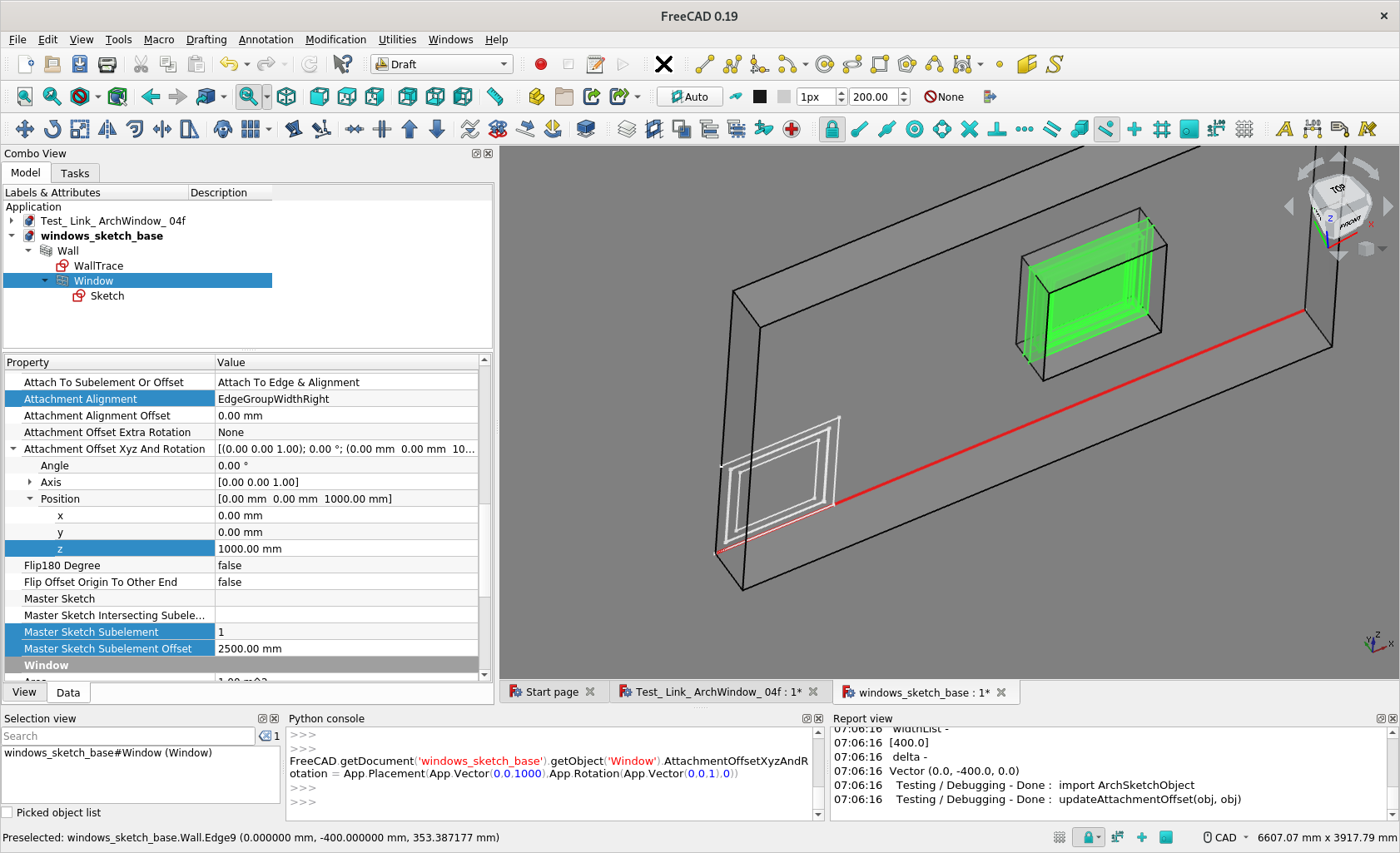
Firstly, make sure your Base Sketch of the Window Object is 0,0,0 (which is not atm) - until I make it work with the Sketch at any placement later ![]() In this position, you see how exactly the Window is created relative to 0,0,0 ( ScreenCapture 1 ).
In this position, you see how exactly the Window is created relative to 0,0,0 ( ScreenCapture 1 ).
Now, you can tweak Window’s Added Parameters for ‘attachment’ e.g.
- MasterSketch Subelement - Default to 1 if not set [ so it is good ]
- MasterSketch Subelement Offset - X mm Distance Along and From one End of the Wall, say 2500mm
- Attachment Offset XYZ and Rotation / Position / z - at a height of Z mm from base, say 1000mm
- Attach To Axis or Sketch - Hosts [ That’s good, it’s default ]
- Attach To Subelement or Offset - Attach To Edge & Alignment [ That’s good, it is default ]
Then it’s fun, if you Edit the base Sketch of the Wall, move / stretch the base edge, the Wall will follow and the Window will follow.
I then add an a few edges to your model, now the Wall has 4 Segments
- MasterSketch Subelement - Set it to 4 e.g.
the Window switch to edge 4.
(Same at 2500mm from end of this segment of wall and at a height of 1000mm from this segment )
( I haven’t discussed about the ‘offset’ from the alignment still ![]() )
)
windows_sketch_base_ r1.FCStd (40.5 KB)


Thanks a lot for your quick answer @paullee … now a lot is much clearer.
In the meantime I also learned how to stick windows on inner/outer wall edges by using the option AttachmentAlgnment=Edge and specifying a proper value for AttachmentAlignmentOffset.
Once you have found your way around all these variables or alternatively we will find a more intuitive way to handle them your tool IMO will be a game changer. Your work is fabulous!
Cheers!
Thanks.
The selection options ‘EdgeGroupWidthRight’ or ‘EdgeGroupWidthLeft’ are supposedly to let user align the Window object to either face of the wall, without manually inputting the ‘AttachmentAlignmentOffset’. I find some bugs or inconsistency.
One problem I hope peoples can comments are in fact the names of the properties, ‘Attach To Subelement Or Offset’ is not quite intuitive or understandable in fact, similarly ‘Flip 180 degree’ etc. See if you can offset some ideas ![]()
I created an issue to better track this feature https://github.com/paullee0/FreeCAD_SketchArch/issues/3
Unfortunately I am not a native English speaker, so probably unsuitable for finding better names. Nevertheless, I will try to do my best and if I find something better I will post it here in the forum.
Cheers
Hi @paullee,
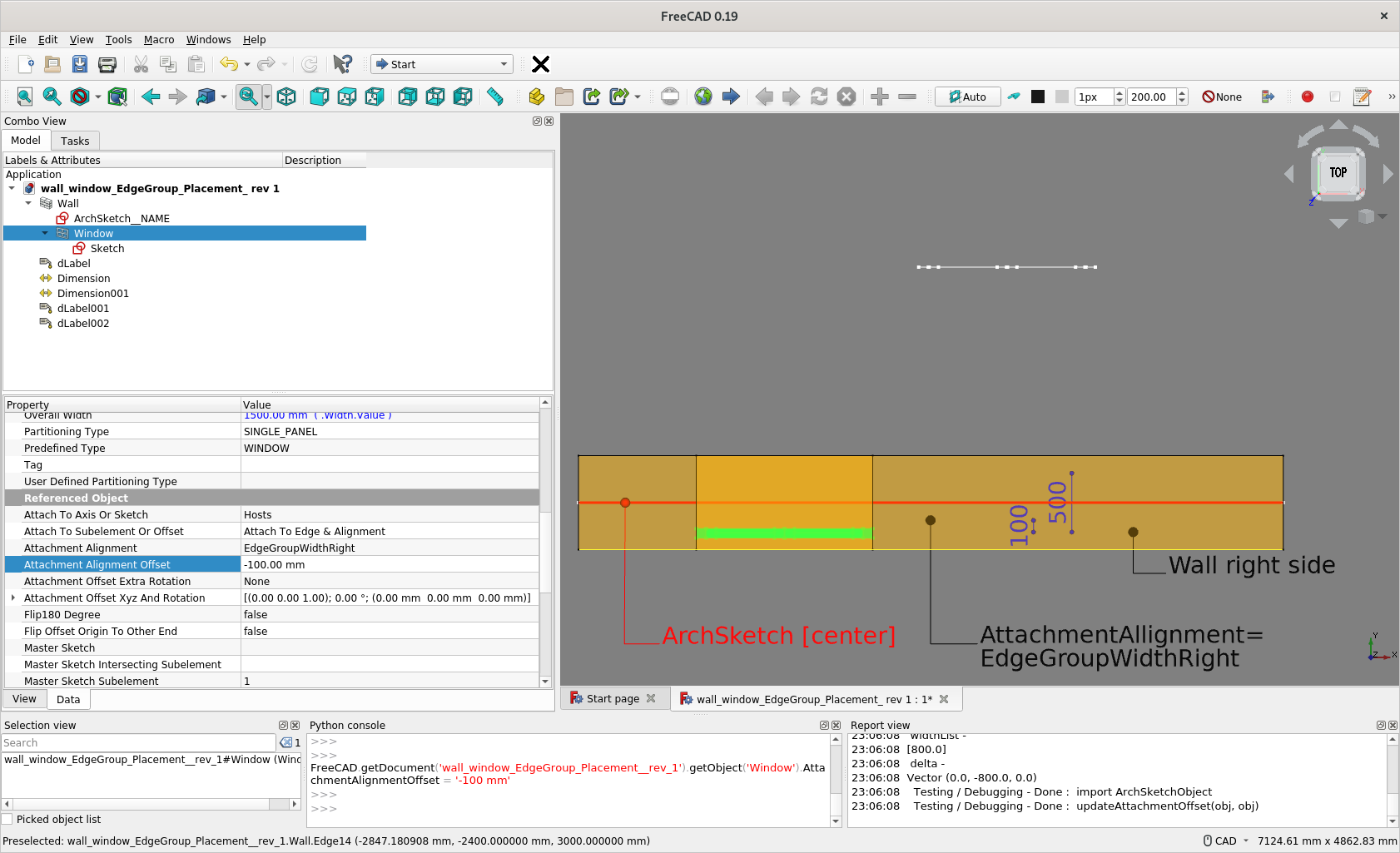
Generally once you get used to the options ‘EdgeGroupWidthRight’ or ‘EdgeGroupWidthLeft’ they work fine … but I find a case where they maybe can be improved. See this example:

The window was inserted with an offset of 10cm on a wall with width of 50cm. The option ‘EdgeGroupWidthRight’ was selected so by changing the wall width to let’s say 30cm the windows continue rightly to stick on the right side of the wall at a distance of 10cm.
But if you change the wall alignment let’s say from “Center” to “Right” then the wall placement changes accordingly but the absolute placement of the window remains the same. I would expect also the window to follow the wall movement … or am I getting something wrong? ![]()
Here is my sample file:
wall_window_EdgeGroup_Placement.FCStd (66.2 KB)
Cheers
Thanks, good suggestion, seems needs lots of calculation ![]()
Thanks for testing again, seems that features has not been fixed yet ![]()
In the meantime, may need manually .set the offset.
See if you want to open an issue.
p.s.
Noted you are tweaking Window built-in parameter Offset.
There is another similar ‘Attachment Alignment Offset’ in the SketchArch Add-on.
You may try to explore any difference and use case ![]()


I thought I figure out how to avoid the necessity to make the Window Base Sketch placement at (0,0,0).
ArchSketchObject.py (50.1 KB)
But it seems in some cases, the Window’s Base Sketch placement still affect the Window placement.
I just can’t figure out the pattern to understand where in the equations fails, see if anybody can try or look into the code ![]()
I think I figure out this time, see if you and anyone would like to test, thanks !
Now, it doesn’t matter where the Base Sketch of a Window object is, with a caveat.
ArchSketchObject.py (50.4 KB)

Hi @paullee, I tested your latest release and for me it works like a clockwork. Thanks for your great work! I really think that it will be used by a lot of users ![]()
BTW I couldn’t resist to input a window “the traditional way”, more precisely using the window insert dialog with the option “Auto include in host object” checked and selecting an input point on the lower wall edge. Then adjusting the parameters “MasterSketchSubelement” and “MasterSketchSubelementOffset” to the correct values. As I noticed we are not far from being able to input doors/windows in a more intuitive manner:
- For walls in global x-direction things already works quite well. Other walls seems still having some minor issues with their placement (see attached model)
- “Sill height” input in the dialog could maybe be written in the z-value of the “AttachmentOffsetXyzAndRotation-Position” variable
- Ideally the variable “AttachmentAlignment” (and maybe others?) could be added to the window input dialog and their changes could give a graphically feedback to the user before the object are placed.
I know I’m dreaming, but I’m willing to give my best to get there. Unfortunately I’m no coder and my contribution for now is limited to testing ![]()
Thank you for your efforts

Direct_windows_input_ArchSketch.FCStd (142 KB)
Thanks for testing really ![]() Indeed, the equation still has some cases not handled - the Base Sketch can be at anywhere, rotation at axis-X is ok, but when rotation at axis-Y or Z, then the equation fails …
Indeed, the equation still has some cases not handled - the Base Sketch can be at anywhere, rotation at axis-X is ok, but when rotation at axis-Y or Z, then the equation fails …
Hmmm… see screencapture and files. And the caveat I mentioned is may need to tweak ArchWindow’s Normal also (0,0,0 is automatic but in opposite direction than the default 0,1,0 )
Yes, sill height is a good term.
Not a dream if someone better in coding, know how to tackle that dialog box, not even need @yorik, can do it ![]()
Direct_windows_input_ArchSketch_ r.FCStd (230 KB)


I really think this time I figure it out ![]() Please someone like to test every corner cases you may have.
Please someone like to test every corner cases you may have.
SketchArch WB / Python Updated
- SketchArch WB in https://github.com/paullee0/FreeCAD_SketchArch
- Or simply replace with below 1 file
ArchSketchObject.py (50.2 KB)


