That’s ok, I think all of us in that thread are not from English speaking countries ![]()
I know, but from your flowchart I couldn’t recognize the flow that gets to conclusion that all the objects should be added alltogether…
That’s ok, I think all of us in that thread are not from English speaking countries ![]()
I know, but from your flowchart I couldn’t recognize the flow that gets to conclusion that all the objects should be added alltogether…
TADA!!!


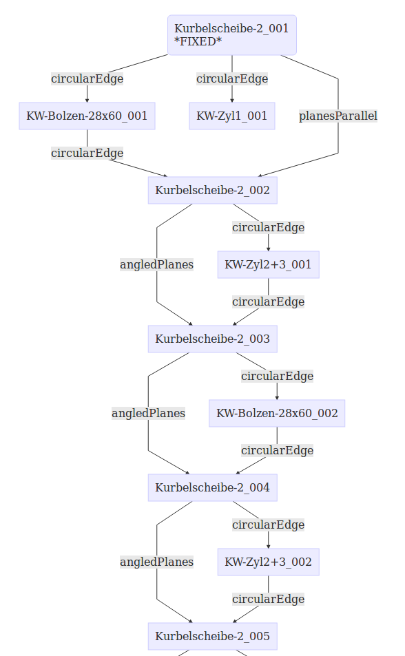

That’s the hierarchy that the algorithm creates from all the rigids and constraints.
Good parts naming will definitely help with those charts…
Those charts are created semi-automatically, have to copy&paste some text to an online tool.
If I will find a way to create a file from within the python, I could create HTML directly from the code.
The addition is based on the code I proposed, so if it will get into main, I’ll PR those additions too.
If we’ll have the dependencies DOF analysis based of Turro’s work, it can easily be added to the charts as well.
@kbwbe
As you’ve communicated with Asm2 owner before, maybe you could ask him if he has some good Asm2 files for testing.
I could try converting them to A2P format.
Hi Turro,
hi project4,
I am impressed more, every time looking at this thread.
Great charts, generated by your algorithm @project4. This is a big improvement.
I will create some very ugly assemblies for testing, directly done with A2plus (“all together mode”). As Assembly 2 could not solve such complicated things. It also could not solve the 6DOF example. Therefore Assembly 2 test files i think would not be difficult enough.
Ok, just thought it could save some work for us.
In any case it might be very useful for old Asm2 users.
We all have the same in common: we need assembly WB for our projects, that’s why there is such a good progress.
I’m sure there are lots more people who use or need assembly in FreeCAD.
I don’t know the history and politics behind the scene, but I don’t understand why Asm2 didn’t go yet into FreeCAD default installation…
Thinking about it a bit more… DOF analysis is definitely THE way to go, but we have to find a way to find groups of parts constrained into a fixed part by several constraints.
To explain, for example, even in a very complex assemblies there are generally parts fixed with screws.
Generally you constrain 2 or more holes with circular constraints and after that add a screw to one of the holes and later a nut on the screw.
The screw and the nut are leafs without children, so those are easy.
The 2 faces constrained with 2 circularEdges on the same axis will leave no free DOF between them and should be considered as a sub-part that can’t be moved any more.
Are we able to recognize that constraints are on the same axis of a plate?
You did the DOF analysis already, but I didn’t really dived into the excel to understand it fully.
I’ll probably get back to it tomorrow.
We need to remove DOFs based on ALL the constraints on an object.
It will help if you could propose a function that takes a rigid, analyse the constraints and returns DOF information, which axis left free (movement/rotation).
@project4:
I need to ask: For your great(!!!) charts, do you extract the object labels or object names of the parts? Sorry for my humble german part namings and even weird abbreviations. I’ve never thought on part and assembly creation that it may help for this project somehow.
For my re-assembled crankshaft in https://forum.freecadweb.org/viewtopic.php?f=20&t=29207&start=260#p245241 (fcstd file: https://forum.freecadweb.org/download/file.php?id=63542) I’ve only changed the labels conforming to @Turro75’s original A to O part naming from his diagrams, like @kbwbe pointed out last evening. So, can be that my changes are useless for you.
BTW, does your chart algorithm also extract “lock rotation” settings?
Manuel
Unfortunately I have no insight on how the current solver handles constraints combining together with the DOF of a part. Is there e.g. an array of pos./rot. DOF values attached to a part file being assembled, so getting more and more constraints? This could be used with a comparable array of “lost DOF”, imposed by a constraint. This way it could be found out what axis or direction is available for rotation / movement.
Manuel
Chance to be merged to master branch is good.
Final code should provide:
Thank you already now for your contributions !!
here a sample code for writing a file to home folder
import FreeCAD, os, sys
from os.path import expanduser

home = expanduser("~")
out_file=os.path.join(home,'myfile.txt')
FreeCAD.Console.PrintMessage (out_file)
FreeCAD.Console.PrintMessage ('\n')
mycontent=['Hello','this is a second line','and then a third']
with open(out_file, 'w') as my_file:
    for item in mycontent:
        my_file.write("%s\n" % item)
I’m thinking about a sum of constraints position and rotation.
let’s consider the sub assembly You just described: two holed plates (A and B) ad 2 screws ( C and D) and nuts (E and F).
consider as areference for the subassembly the plate A, this is fixed while B is free in the space
based on this chart:

B dof = 0,0
first put plate B on top of plate A by creating a plane constraint which locks 1 position (normal to A) and 2 rotations. in fact B can slide in every position of A.
B dof = 0,0 + 1,2 = 1,2
second create a circular edge constraint between an hole on A and an hole on B. now B can still move but only rotating around the axis of the hole.
this action should remove only 2 position dof while circular edge removes 3 pos and 2 rot.
B dof = 1,2 + 3,2 = 4,4 (?fully constrained?) overconstrained?
third create a circular edge constraint between an hole on A and an hole on B as did before, this time the plate is fully locked in position as even the third rotation axis is locked
B dof = 3,4 + 3,2 = 6,6 (fully constrained) overconstrained?
this is weird, based on basic math after the second constraint everything should be fine as both pos and rot are 3 or more.
in fact to get the same result the right way should be:
B dof = 0,0
circular edge constraint (3,2 dof lost) on a hole between A and B
B dof = 0,0 + 3,2 = 3,2
create a point on plane/point on line/point on point between A and B so 1 dof is removed as the plate cannot rotate anymore around axis normal to constrained hole
B dof = 3,2 + 1,0 = 4,2 (fully constrained)
this is the way how asm3 worked at the beginning, solvespace punish You if You overconstraint the objs, a special handling was created to avoid this.
since screws and nuts are cosmetics , are usually inserted at the very end of assembly and as they are dead branches it would be easy catch them and solve them as individual (items without sons constrained to fixed parts).
this is very though as it is not only related to the constraints type, it depends also on what receives the constraints.
further analisys could be create a chart which defines exactly which dof is locked X, Y, Z, Rx, Ry, Rz for each constraint on each element.
this table could be an example (the number is the dec base of the dof as binary), but if I apply a bitwise operator OR , the sample above never results as fully constrained. this table changes if the constraint is joined with another constraint, and this is only related to an assembly composed by 1 father and 1 son…

Any alternative idea is welcome, the math needed to solve this is over my knowledge.
@Turro75:
I don’t get your point to put it into ONE value.
Why don’t you think of a two-row array of x y z constraints for position and rotation?
Maybe one array to use for binary operations with constraints, and to determine remaining DOF of a part, and let another one reflect the parts move/rotate vector.
Manuel
Please take the changes from my branch (don’t know how you do it since I didn’t PR them to you).
I’ve added a fix to some looping situations.
Now the 6DOF hierarchy is more accurate to the assembly relations:

Hi,
Yes, I’ve changed the code to use labels instead of objectName and here’s the chart for the file you sent.
I think we better add the DOF analysis to the code, so we could have the automated charts out of the file to see how the algorithm sees them, that will probably save a lot of manual work.

I can add any known info to the chart. Since lock rotation is not handled, as kbwbe wrote, I think there is no point to print it at that time.
Hi Manuel,
please can You provide an example?
Hi project4,
brilliant job!
Thanks!
I’ve update the code to create “assembly_hierarchy.html” file in home directory.
Please tell me which of your branches is the correct one ? Only one file changed ?
Edit1
Found branch. kbwbe/A2plus branch abetis-1 is up to date
/Edit1
@project4
Great job. All standard test are working.
Just detected another big problem within basic solver algorithm.
I tried to assemble the first “real world” project. A machinery frame with some bigger dimensions. Some parts are about 2 meters long.
This assembly i want to use as one more standard test. This assembly can be extended with other connected frames.
I cannot assemble it. All solver variants fail during 2’nd constraint. Sure a problem with basic algorithm. Something seems to depend heavily on size of parts.
I attach the parts which i try to assemble within a ZIP. (including the failing assembly with two parts)
Whole Frame looks like something as this when ready…
.
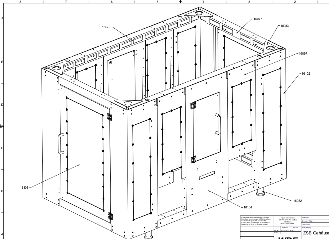
.
I will have to check all mathematics !!!
Machinery-Frame.zip (162 KB)