Nice. Ok just so I understand, this is your outlining of the circumstance that leads to this, right? There’s not an expectation that the shape that serves as an extrusion’s inspirations be moved around with the extrusion, right?
Maybe there is such an expectation.
As you had drawn it, I attempted to make it work with the underlying door rectangle at 90 deg to the plane but failed. Nothing I did would make the cut work. The moment I rotated the door shape to lie along the plane (and subsequently corrected the extrusion), the cut as expected seemed to work.
Maybe there is a need to have a separately aligned extrusion inspiration for each extrusion plane.
Roy_043 in the previous post (and currently I agree with him having re-looked at your first post house available to download today) suggests, there is possibly some underlying issue not presently evident that stops the cut working. Like Roy says the cut isn’t working.
I’m off to retest separately various panel cuts with plain rectangle inspirations for cut extrusions with the inspiration inline or at 90 deg to the intended cut panel to see what currently works. I’ve always placed the inspiration, with the resultant extrusion straddling the object plane where I need the cut. Maybe rightly or wrongly in that line of action.
Hope this helps.
Hi OverkillTASF,
The plot thickens. I’ve been idly watching telly and trying out some combinations of Inspiration (underlying rectangles), subsequent Extrusions and an Arch Remove cut on a Panel. See attached file.
I’ve left all the rectangular inspirations and cut extrusions visible in the file so it is easy to see the alignments and separations.. Also I tested inspirations aligned to the panel plane and at 90 degrees to the panel.
The key takeaway I’ve noticed is that if the underlying inspiration is separated from the extrusion, the cut fails or is misplaced. This unfortunately seems to confirm the expectation that the extrusion must follow / be coincident with the inspiration for a successful cut. Probably not the result you expected or wanted. Alternatively, I’ve have not experienced such issues because I’ve always positioned the inspiration with each extrusion.
Hope this further helps. It has certainly has increased my knowledge in this area.
Cheers. PMac
A00120001PanelCuts001.FCStd (37.9 KB)
Now I’m having issues moving Beam077 vertically. It will become an LVL header for the garage door span, but I’m unable to move it up or down… Still running 22336.
The key takeaway I’ve noticed is that if the underlying inspiration is separated from the extrusion, the cut fails or is misplaced. This unfortunately seems to confirm the expectation that the extrusion must follow / be coincident with the inspiration for a successful cut. Probably not the result you expected or wanted. Alternatively, I’ve have not experienced such issues because I’ve always positioned the inspiration with each extrusion.
That’s gotta be a bug! If multiple extrusions are based on / inspired by one “profile” shape, which one should the profile move around with? In any case the Difference tool seems to do the trick.
Ah, oops. I had done some parametric-stuff in the position of a window header and copied a window header to base this one off of, and forgotten. So the Z was set to a specific height based on other measurements. Resolved!
https://gitlab.com/Tyler-2/starter-home/-/blob/b35185b6fd65b6c7d48adf7b15ec577bd9a860ac/starter-home.FCStd

Last bedroom window framed, header placed (until structural engineer has better details) on four uh, cripples I guess. Note that the sole plate and all of the vertical framing/windows in that section will be removed when it comes time to convert to “garage” mode. Planning for that, while also still trying to get 4’ centers for my sheathing to land on was a little frustrating…

Panic this evening… I threw together a 2-shipping container storage area that I need to get a building permit for… and I’m having an incredibly difficult time getting section views to work appropriately. I end up with items missing, weird render errors… It has me very worried that all of this work will result in something presentable… Is it folly to try to have my elevations and whatnot rendered in techdraw sheets? What stage is best for adding dimensions?
Added wallboard all around.

Now it looks much more boring given all the work that went into framing, but that’s life I guess.
At this point I’d like to draw the interior rooms just as non-structurally accurate walls. I find Inkscape is a lot easier to do this, and that’s where I did my first original plan. Drawing a wall and up against another wall and then bumping it X inches down without worrying about 3d space is a better workflow when doing floor planning. But I guess I’ll try to do it in the draft workbench…
Still really worried about getting the cross sections out of this that I’ll need when I submit it to the planning dept…
Found a problem with the rear wall wallboard… went in to fix it… and also discovered that when you move a panel that has had a subtraction done on it, the volume you used for the subtraction also is moved. Which is really unexpected… at least in this use case.
Not suuuuuper happy with the flexibility of the section views… For instance I’d like to be able to cross hatch cut areas as is the convention. Not sure why the defaults make cut lines BOLD either… but with some tweaking I can get that to look basically right. Adding dimensions here is a lot harder and weirder than I expected, as is adding callout lines and labels… maybe I’m missing something.


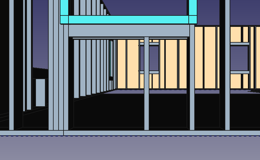
Here’s the left side (which will be the front of the house, really) with the sheathing removed.

The weird framing is so that the wall can be torn out and a garage door installed at some point in the future.
I read this. I have been very interested in the use as an architectural drawing tool. It was interesting to watch the house take shape.
My first steady job was using my construction training in an office was using Softplan to draw houses, so I tend to draw everything in my head in a Soft plan manner. Exercises like these are helping me rethink my processes.
About some terms:
Short studs above and below an opening = Cripples
Tall Stud next to an opening = King Stud ( a few other names around the country)
Short stud next to king stud that holds up the header = Jack (or Trimmer)
Fantastic progress so far. Great to see the effort you’re obviously applying and learning along the way. Good to see the incorporated future garage door framing with plenty of room for lateral in-plane bracing allowed at each side of the garage door.
For eaves overhangs, like cut-down rafter ends, this is how I do it. Create an XZ plane sketch for each different overhang shape. For example, a 240mm deep rafter might extend 500-600mm as an overhang past the supporting top plate, with the overhanging eaves underside part being cut away to form a stepped 90mm rafter overhang. Detail the sketch so that the rafter length and overhang lengths are separate but easily changed. Also set rake/slope angle to future proof any changes. Extrude the sketch by 45mm to form a nominally 240x45 thick rafter base object of your desired shape. Hide this base object. Clone each of your rafters (Arch/Clone the hidden base object each time, do not form one clone and try to copy) and position each rafter as required (eg at 1200mm centres/spacing) along the building length.
Hope this helps, P.
I’ve found that a lot of terms are regional which makes talking about this on the Internet a real PITA!
The terms you’ve used are the ones I’m familiar with too, though! I’d probably have better naming if I had an easy way to bulk rename objects.
Can you share a file with this illustrated? I’ve got this problem right now:

… For eaves overhangs, like cut-down rafter ends, this is how I do it. …
… Can you share a file with this illustrated? …
Have attached demo file with rafters as requested. The demo file is taken from a much larger personal project I’ve got on the go. The rafters shown only cover one half of the house - I haven’t drawn the others to date.
Anyway, you’ll see the rafter bases (hidden) are drawn from underlying sketches. These sketches are drawn on the XZ plane. The sketches are positioned in the XZ plane to match and sit on the top plate positions. Note that the sketches are not mapped to any part of the structure. The rafter base sketches are then extruded by the single rafter thickness (45mm) to form a specifically shaped rafter base which is correctly positioned when looking at the Front view (XZ plane). The overhangs and fine detail like birds mouth seat cuts are detailed in the sketches, including the 10 degree proof pitch.
From each of the specifically shaped rafter bases with underlying sketches, the actual rafters are individually cloned. From there each cloned rafter is positioned as required along the Y-axis. Individual cloning is tedious, but has the advantage that if I decide to change the pitch, rafter length or overhang in the future via a sketch alteration, all the clones will immediately change. The rafters in this project are nominally 2x240x45mm closely nailed together to safely cover the span and are nominally placed at 1200mm centres.
As for your other issue - bulk renaming. I breakdown all my structure objects with creative naming and place them in their respective groups. You end up with a lot of groups, but it easy to hide groups of things like internal or external walls. Within each group, I usually select the first item, making sure the last part of each item label is a number like “001”. I then copy the label text of the selected item to bulk label the other group items. The number at the end will automatically increment over the item group.
Hope this helps, feel free to raise further questions.
I too am learning, having my own issues in other areas and have been watching your project closely to see how others solve issues.
Cheers Peter.
A00150014RafterDemo001.FCStd (153 KB)
Oh MAN. I had been selecting multiple and then right clicking to rename. Not that your post made it clearer but you were saying it is possible which implied there was another way to do it. Therefore I now know… :
To bulk rename objects in FreeCad, select them, and then modify the Label attribute in the Data view. Do not right click and rename, that won’t work.
Happy to assist.
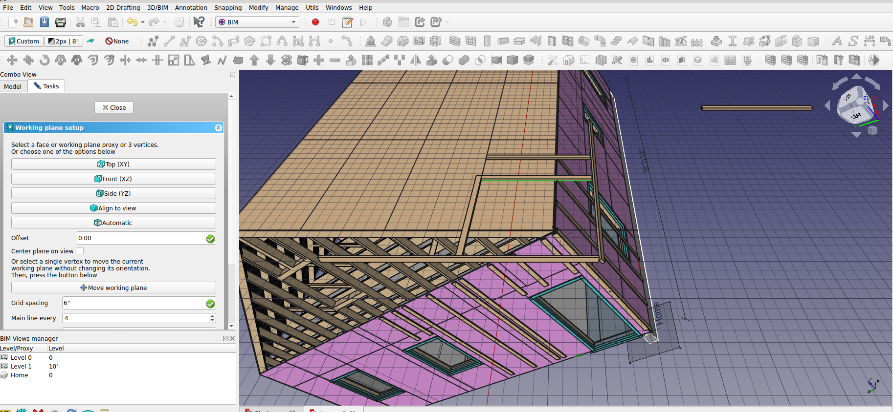
I haven’t gotten a chance to look at / try your rafter cut technique.
Right now I’m trying to work on some details on the roof surface.
Instead of looking at the front, left, right, or top of the roof, I need to look squarely at the surface of the roof. So that up the roof is Y, towards the ends is X, and directly through the roof is Z.
I don’t know what this is called, or how to do it…
Ah, I think I figured it out…
To change the working plane and view to the face of an object:
- Go to the Draft workbench.
- In the Utilities menu, pick “Select Plane”.
- Click “Move working plane” and pick the face of the object you want to move the working plane to.
Now the X/Y/Z are aligned with that object and if you pick “center view” your view will be rotated in line with it too.
PMac, I Got a chance to look at your rafter work.
It looks like essentially you do a custom sketch of the rafter profile and extrude that. I can definitely see how that would be easier than some other methods! But if you want to make the rafter longer you have to go edit the sketch right? Man I’d love to just be able to be able to say this is a 2x4, 14’ long, and the end is cut at an angle like “this”.
I guess I’ll need to go that route. Thanks! Sometimes knowing that other, possibly smarter people, are doing things the way you thought seemed dumb, makes you feel like maybe it wasn’t such a bad idea afterall…