An open source home in the BIM workbench

I’m building (well, only planning at this point, obviously) an energy and materials efficient, simple, small home for my family of 4, which meets my local building codes, and can be converted to a garage in the future when we build a larger home. It’s my intention for this to be contributed as “open source” when I’m done.

I had originally done the floor plan, framing plan, and elevations in Inkscape, but keeping the various views up to date meant edits in multiple dimensions from multiple views and damn… it was a hassle.

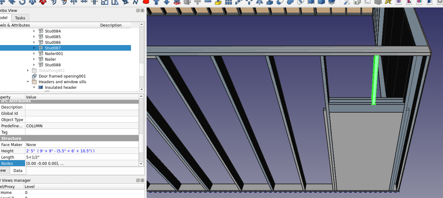
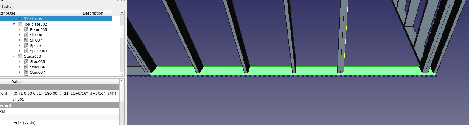
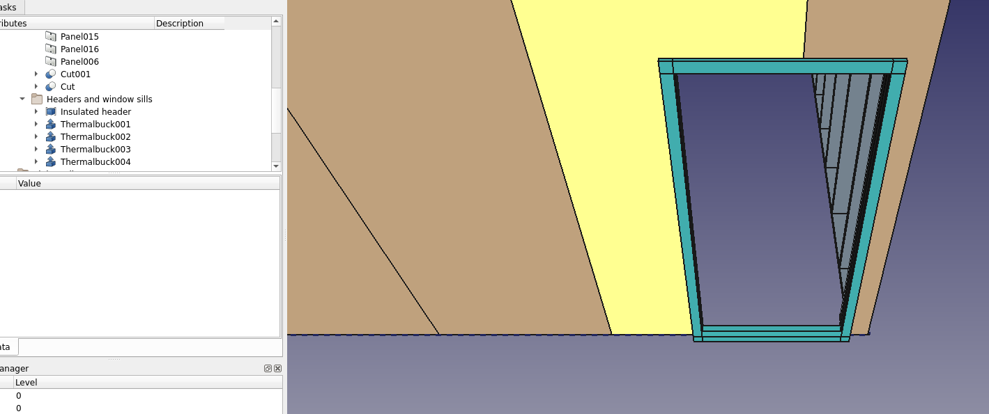
I’m hoping to build this in Freecad to make my job easier, but also to learn more about Freecad and the right way to use it for architectural / structural drawings.

Unfortunately I’ve drawn this thing probably 15 times, always finding an impassable limitation to how I had been doing it that convinced me my technique was wrong in prior iterations. So here we are now.

I’ve dropped this into Git just to conveniently do public versioning:
https://gitlab.com/Tyler-2/starter-home

Features planned and implemented:

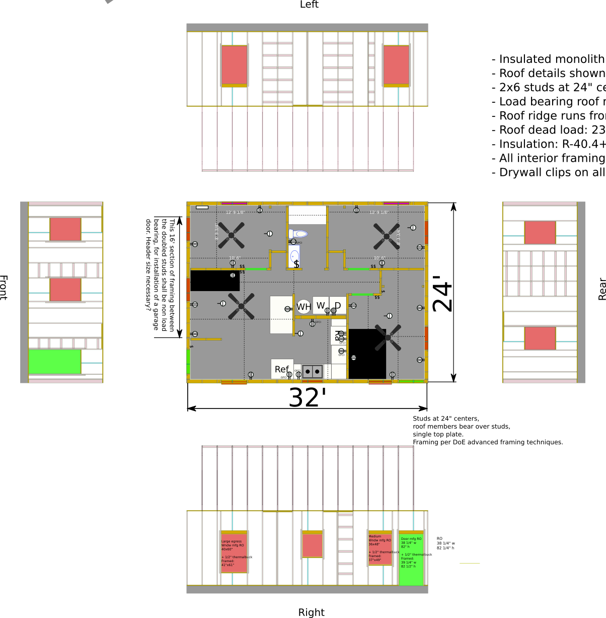
  • Following US DOE Advanced Framing Techniques. 2x6 studs on 24" centers, single top plates, studs in alignment with roof members all the way to foundation.
  • Insulated foundation, probably slab on grade.
  • Exterior insulation, insulated vented roof with air sealing details.
  • Convertible to 2 car garage with work spaces or guest room with minimal effort. Removal of some non-structural framing, movement of some plumbing fixtures, installation of garage door.
  • Architectural style that fits with ranch style home.
  • 3 bedrooms, 1 bathroom.
  • 10’ ceilings with conditioned attic space.

https://gitlab.com/Tyler-2/starter-home/-/blob/3e98ce02efe137f05555612b7b292ad47b1e6472/starter-home.FCStd
Screenshot_2020-09-12_19-00-39.png

  • I have been unable to figure out a good way to make any of this meaningfully parametric. Would love some tips on that.


  • How can I make a movable “hole” in the framing? Or, failing that as a possibility… how can I do a one time cut operation? Notice the slab overlapping the framing in front view… Not that it’s placed correctly here, but I wanted to use it to cut a hole for the door framing.

Add some images. It’s faster to see, instead of downloading and opening your file.

See this as well:
Small house design workflow with Open Source software (work in progress)

Added a screenshot of that first revision, thanks.

FreeCad seems well suited to generically do walls, but not the actual framing/structural details inside those walls. I’m trying to make sure that the structural details are available. Additionally, I’ll need to provide cross sections and drawings that show flashing details etc. The workflows are quite different I think.

Here’s a PNG of what I had done in Inkscape. You can imagine why it was such a pain to keep up with… Also I’ve had to make the whole thing somewhat larger, and noticed some mistakes in my stud layout. So this is very much obsolete.
Original-plan.png
When I first started doing the overhang and truss design (Trusses designed by a third party) I had to do that in FreeCad since Inkscape couldn’t handle the angles. While what I did looked right… and the truss design was a totally parametric, fully constrained sketch… None of the other pieces are constrained to each other. So now that I need to make this 2 feet wider, I have to redo so, so much!
Screenshot_2020-09-12_19-02-28.png

Hi again OverkillT,

I have been unable to figure out a good way to make any of this meaningfully parametric

I see this as a sequential problem well suited to a customised macro (or a series of macros or even a custom Python module).
Known constraints:
Required wall framing size is known.
The drawing starts at an outer stud corner on the floor at a known base point (0,0,0), so draw a bottom plate here. All subsequent measurements are locked to the base point.
Any wall is a known length - allow for side walls thicknesses if required.
The number of bottom and top plates is known as is the required wall height - this sets the stud lengths.
The wall framing is repetitive of a certain stud size and spacing - easily drawn, including doubling studs and top plates where required allowing for commercially available standard timber lengths.
Add side walls and then rear wall - all are from the base point.
Add linings and cladding as required relative to established base point. Again available sheet sizes may dictate positions.
Problems - where do you put studs with odd centre-to-centre spacings? One end of wall run working with full sheet sizes as much as possible or at each end equally spaced and how do you make that decision? A similar issue arises below with increasing the width of your gabled roof by 2’. Do the studs start at the end or are spaced from the centre of the gable?

How can I make a movable “hole” in the framing?

I too have wondered about that. Sure you can draw a cut volume as you’ve shown for your personal access door in your drawing, but AFAIK each stud (and other framing) must be cut manually.
Problems I’ve had are cutting raked studs in gable ends - the moment you cut them to get pretty drawings, you lose all the stud length information required for a quantity survey. What I do is manually adjust each raked uncut stud to have about 5mm of overlap to the above raked plate thus preserving the stud length info for costing. It would be really nice to draw a raked line and cut every stud that it crosses, without losing the length info.
FreeCAD already does this with cut volumes turning all selected items into a single cut item thus losing all quantity info. Sure, could write a custom macro to cycle through each selected stud to overlap the raked limiting upper plate - a lot of work. A similar problem exists for birdsmouthed rafters based on a sketch in that there is no quantity information.

I avoid arrays of anything like joists, studs, nogs and linings as AFAIK you cannot get quantity info from the array items or reposition individual items easily.

On one of your drawings, a garage header/lintel size is queried. Here in NZ, garage header/lintel fixings over wide spans pose real problems. A seismically active country often coupled with high gable-end wind loads fixings for a 16’ (4800+mm) span like this often require specific engineering design by a structural engineer. Getting the header/lintel loads down to the floor is often a fixing problem. Header / lintel to top-plate level fixings also need close attention for potential wind uplift loadings.

Unfortunately, a lot of customised coding/decision is required to make it ‘parametric’ making building a very manual process.

Hope these comments help, I will be watching this thread closely to see what else falls out from other comments.

What are the ladder-like wall frame sections intended for? Support for built-in cabinets?

PMac: Oof. I feel like you might be right. The only way I can conceptualize making these things parametric, and not even fully parametric, is that there are some framing members that have obvious relationships to each other. Sills and plates that are end to end to each other or join on corners. Studs that are always on the ends of sill plates, studs that are always 24" from each other, etc. I love doing constraints in the Sketcher. Building the trusses was actually pretty cool, but that workflow doesn’t translate to a full 3d building. I think the “Assembly” workbench could end up making sense, with each stud being a part or something, but I’ve not seen anyone use it for this, and I just can’t figure out how to use it. It’s possible that doing this parametricly just isn’t doable without, like you mentioned, scripting. Which I think is beyond most users including myself.

PMac: Do you know how I can cut the structural sheathing and other sheet goods like the insulation and siding that are coming? It’s easy enough to “cut” the studs by changing their lengths (though very manual), but I can’t figure out how to cut the necessary holes in the structural sheathing.


Those are where the interior, non structural framing members will attach. Typically you’d just make another set of studs with blocking… but that’s more wood, and wood is poor insulation. Page 4 here gives a little blurb about it.
Screenshot_2020-09-13_07-53-41.png

https://gitlab.com/Tyler-2/starter-home/-/blob/af964d7134a39185eb64cb3c40807c8d8a2ad7aa/starter-home.FCStd

Since it doesn’t seem like there’s a great/better way to define these things parametricly, I went ahead and put in the framing for the bedroom exterior door. Note that the frame is larger than typical. The door manufacturer calls for a 38-1/4"x82" opening, but I’m also using the Thermal Buck product to pull the door frame to the exterior through the foam insulation. That’s not depicted yet… But the thermal buck is 1/2" thick, hence the larger opening. I had considered not using the thermalbuck on the bottom part of the door since the floors inside will be unfinished and adding another 1/2" step-up to the door frame felt silly. But it might simplify the support of the bottom of the door sill…
Screenshot_2020-09-13_08-59-37.png
I’m not actually sure the nailers are necessary… but I might leave them just for a little more security of the edges of the Zip sheathing…

So now I’ve got a stud that I need to be shorter. It needs to hit the top of the header, obviously. I could do some math in the data dialog… which is what I did. The stud needs to be (stud length - (door opening height + header thickness)). And then it needs to be moved up.
Screenshot_2020-09-13_09-11-28.png
While that works, the numbers entered aren’t really tied to anything else which is silly. And it’s hard for the drafter. It would be a lot easier to “constrain” it by saying “This stud needs to be long enough to span between these two members”.

I’ve also done this with formulas using the .height etc parameters… but the difficulty in building those queries kills me, especially the fact that you have to use the internal names of the objects and not the names you’ve given them, and there’s not a great way to build that info.

And I just realized I didn’t cut the sill plate like I should have. So I have to go in and manually tweak these things again.

This is usually the best way of keeping things parametric. You can use the Object’s label, you just need to enclose it in brackets, <>.Height.

And of course, you can use a spreadsheet to collect all such variables.

This is further explained in Expressions. The Spreadsheet Workbench is essentially an interface on top of the expression engine.

There is a workbench or macro that does what you want, have a trawl through the user showcase or news and announcements.

I’ve seen some thing that even works out how to cut the gyproc for minimum waste.

Nice to know that I can use <<>> for the friendly names. It’s definitely still a pain in the butt to do <<Door framed opening001>>.Height + <<Sill002>>.Width + <<Beam043>>.Height / 2.

  • Is there an addon that adds more robustness to the formula authoring, like maybe the ability to click an object, or a larger dialog for building formulas?
  • How can I reference the X position of something? I can do .Placement but it appears to be a dictionary with Pos and Yaw etc, and I can’t do .Placement.Pos.X.
  • Is there any way to reference “the minimum Y” of an object? Some things are placed by their centers, but often I just want to say basically “From the bottom of”.


I’ve used the BIM and Arch workbenches which seem the best developed and supported… If someone’s got a specific recommendation that works well, I think PMac and I are definitely open to it! But I don’t think either of us have found the magic sauce.

PMac: Do you know how I can cut the structural sheathing and other sheet goods like the insulation and siding that are coming? It’s easy enough to “cut” the studs by changing their lengths (though very manual), but I can’t figure out how to cut the necessary holes in the structural sheathing.

Hi Overkill,
See attached file for examples of cuts.

I use the Arch WB Cut with a Plane, Cut with a Line and also the Part WB Cut with two shapes.

Some observations:

Note that all the above cutting operations only work with selecting one shape to be cut and one shape to place the cut line. As can be seen from the attached example file, this makes cutting nogs and panels a tedious manual process of selecting one nog or panel, then select one cutting line or volume, then doing the cut.

If you want pretty red ends to your cut studs - make sure the cutting volume is red or your colour of the day.

Applying a cut to a nog which is fully covered by the cutting volume will cause errors. Don’t do that - just hide the nog.

I suspect that if I changed underlying shapes of the cuts, eg stud spacings or panel texture, sometime later the cuts quickly would turn to custard necessitating reworking the cuts on that shape. This was particularly evident when I tried to apply to the corrugate texture to the previously plain vanilla flat panel that had already been cut with the raked line. The newly textured panel required all cuts to be re-done.

To automate these typical cuts as a ‘parametric’ process would require some serious code. Hence the reason I keep falling back to manual creation of studs, nogs and panels, all uncut to preserve quantities for future costing.

I also only use beams and columns for plates, studs and nogs - these in the uncut versions have initially hidden structural nodes which may be useful for loading analysis operations down-track, especially in the verification of load paths from the roof to the foundation. Your afore-mentioned building code already takes note of this by requiring trusses to be over stud as a rule of thumb. Future iterations of FreeCAD could utilise these built in structural nodes to help verify load paths via the FEM WB.

One thing I would like to experiment with long-term is to make full use (as you also suggested) of the Assembly features. I see the App::Link feature as showing promise where small easily detailed assemblies like a single internal door with all of its associated wall framing could be separately detailed in a possibly fully parametric file which is linked into a main model file. Any subsequent changes in the small file are then rippled through to the main model. Repetitive and easy to control versioning of small parts whilst hopefully retaining full quantity info per assembly.

Hope this helps.
A005-0021 Sample Wall Cuts 002.FCStd (289 KB)

  • Is there an addon that adds more robustness to the formula authoring, like maybe the ability to click an object, or a larger dialog for building formulas?

Not that I’ve seen. ‘A larger dialog’ to me is scripting via macros and custom Python modules. However I do see spreadsheets as the ultimate way of taking often hard coded variables (quick and dirty, but really poor coding practice) out of the macros and modules whilst providing a well understood functional user interface to change ‘parametric’ values. I considered coding dialog boxes for user inputs but that is just so tedious coding for little gain.

  • How can I reference the X position of something? I can do .Placement but it appears to be a dictionary with Pos and Yaw etc, and I can’t do .Placement.Pos.X.

See attached macro for creating a single door - I’ve been using the Placement fields for position and rotation. (Feel free to utilise macro)
This macro is very much an unfinished work in progress for testing ideas with much potential which will probably get too big.

It also shows execution timings of each section - base layout of macro purloined from a DeepSOIC macro as noted.

Also note that the core wall framing ‘parametric settings’ are hard coded into the macro - I started with just the actual numbers, then added the formulas and now can change say the door width or stud sizes which changes all the framing on display.

  • Is there any way to reference “the minimum Y” of an object? Some things are placed by their centres, but often I just want to say basically “From the bottom of”.

Again, not that I’ve seen. Would be nice to place studs and flat panels from their corners. I just live with the inconvenience. Flat panels are a sod as when they are cut to fit a narrow space - a typical operation - the previously nicely positioned panel now has a new centreline which throws the panel positioning. I see panels are a prime case of where corner positioning should be utilised.

Cheers.
SingleDoor.FCMacro (19.1 KB)

Maybe this Macro would help you a lot :smiley:

Good luck.

Automatic Light Gauge Steel Frame Creator macro

Just tried it and it also can’t be applied to an array. Awesome. So there goes my use of arrays for sheathing and studs!


Are those nogs just horizontal blocking for shear support?


Oh man… it helps keep my hope and expectations very low for what I’ll be able to do here. It feels too late to go back now, but… yeah it looks like everything you’ve discovered just points to pretty much manual fiddly work.


I haven’t looked into using macros yet, so using it is new to me. I’ll try to check it out soon. Thankya’!

Oof. Frustrated that I can’t easily shorten this sill plate to end at the highlighted stud. Scale won’t work. I instead measured the distance with the dimensioning tool and then subtracted that from its existing length.
Screenshot_2020-09-13_23-27-28.png

https://gitlab.com/Tyler-2/starter-home/-/blob/318a410a65906b89f96ddf18b48f23817f9cef4b/starter-home.FCStd
fixed dims
https://gitlab.com/Tyler-2/starter-home/-/blob/8d9e8bee955049cfc21b417a9a6cd4044b50f528/starter-home.FCStd

I used the Difference tool (In BIM workbench) and an extrusion of my doorway dimensions to cut the two panels that needed to be cut for this door. Threw the profiles of the 1" Thermalbuck in and extruded those, placed them properly on the surface of the sheathing. Couldn’t figure out a good way to bevel cut the ends at 45 degrees that would still allow me to scale if I have to make tweaks later. Also lowered the door opening to the floor like it should have been.
Screenshot_2020-09-13_23-53-15.png
My window openings on this wall will be the same height as the door. Is there a parametric way to place headers at the same height as the door headers?

Are those nogs just horizontal blocking for shear support?

Nogs provide lateral stud support - stops stud rollover within the wall when loaded.

The NZ building code allows residential buildings to be built without external sheathing plywood (unlike you do in the US under the IRC or other codes where all external surfaces are often ply sheathed), so studs need lateral supports at a maximum of 1350mm centre to centre. These are commonly known as nogging and in line with the Aussie term sometimes are called dwangs. (Our building codes and standards are very closely aligned. NZS 3604:2011 and the ANZ 1170 series) Note that in NZ extra high wind zones (55m/s / 2.5kPA ULS / about 200Km/H) a ply sheathing is mandatory as a Rigid Air Barrier. In lower wind zones, a building paper suffices between the cladding and the framing as a general air barrier. NZ roofs are typically unsheathed with plywood, just trusses/rafters, purlins on the flat, roofing underlay and the roofing material.

The required lateral support can also alternatively be typically provided by the external cladding eg weatherboards. Internal linings (often 10mm gypsum / drywall / plasterboard) also contribute to lateral support.

Often manufacturers of external vertically aligned sheet claddings specify a max nog centre-to-centre of 600 or 800mm (and 400mm stud centres) to properly support their product.

Plasterboard manufacturers here in NZ typically produce 2x sheet widths - 1200mm (4’) and 1350mm (4.5’) in various standard lengths. Production housing uses 1350mm sheets laid horizontally to minimise plastered joints, provide increased lateral support - these result in 2700mm (9’) high rooms for efficient usage. 1200mm sheets give 2400mm (8’) minimum height rooms.

Cheers