An open source home in the BIM workbench

That’s an impressive implementation. Definitely looks like I’ve been trying to re-invent the wheel! I really like how the short macro drives into the larger Python module which has plenty of potential for expansion into a timber based framing option.

Thanks.

Oh man… it helps keep my hope and expectations very low for what I’ll be able to do here.

Never ever give up. In a previous life I tried being an electrical draughtsman for a short couple of years. The concept of 3D modelling is very hard for me to get my head around - I was used to pen and ink 2D drawings with all layouts, dimensions, notes etc. on a single sheet (the mechanical guy was still doing A0 drawings in pencil). Here in FreeCAD the 3D model usually has no annotations with now all dimensioning and annotations done elsewhere - either in TechDraw or in a 3rd party package.

I’ve always retained an interest in drawing things like buildings - along the way I’ve learnt how to code computers by keeping trying out my options in various programs. I’d be rich if I had a $1 for every dead-end rabbit hole I’ve been down tearing my hair out trying to do things.

Again, continue to try out your options/limits in FreeCAD. If you can contribute in the longer term, even like in this collaboration, you may help another trying to get their head around what works. Remember, once we were all FreeCAD newbies.

Cheers.

https://gitlab.com/Tyler-2/starter-home/-/blob/3a3c3cc53860f1651f74d1b22f75b62af83f15b9/starter-home.FCStd

I finished the structural parts of the “front” of the house. I am not super enamored with that entry door (which isn’t the main entry door) location aesthetically… but don’t really have the room to move it further inboard. The perils of a small home design…
Screenshot_2020-09-14_13-39-14.png
Screenshot_2020-09-14_13-38-52.png
I also did my first section view. I wonder if there’s a way to make it only show the objects that pass through the section?
Screenshot_2020-09-14_13-39-30.png
But the wife decided she was fine not having a door in the bedroom at all, which saves money… so I just made the window that I forgot to put in there bigger.
Screenshot_2020-09-14_14-35-21.png

https://gitlab.com/Tyler-2/starter-home/-/blob/4267c97e5eeca421579d6cce03c016a962a9543f/starter-home.FCStd

Got a little more of an optimized workflow for doing my windows… But it’s not great.

Finished the right side windows. Found that using the Subtraction arch property works pretty well and easily. Started using that instead of the Difference tool.
Screenshot_2020-09-14_17-06-26.png
I don’t know anything about garage door framing… and the left side, while it won’t have a garage door yet, the ability to easily add one later is part of the build requirements. So I’m probably gonna leave that bit undone and see what the structural engineer has to say.

  • Any videos out there that show a good way to do a truss assembly? I’ve done a whole truss in the sketcher which is awesome but isn’t extrudeable to dimensional lumber because, well, it’s multiple solid pieces. When you use the option in sketcher to copy external geometry, does it auto update as the external geometry moves around? I’m assuming not.

I also did my first section view. I wonder if there’s a way to make it only show the objects that pass through the section?

Hi Overkill, your design is progressing fast. Looks good.

With the Section you can resize the section area and change the position to cover the area you are only interested in seeing in the section. Once sized/positioned, turn Section Plane Clip to True. Instead of a Fit All type section planar area, now you’ll have clipped section planar area only showing what you want to see.

Recompute the Section and the TechDraw Page to force the clipping changes through to the TechDraw drawing. Sometimes TechDraw pages won’t update properly.

Note the changing the Section to clipped may make your TechDraw drawing page slow to initially properly redraw the clipped section.

Also as general note, whilst making any large changes to your 3D model (the main drawing) turn the TechDraw page Keep Updated to False. You’ll speed up your 3D Model alterations as the file gets bigger. This disconnects automated updates of the ever-changing 3D Model info into the TechDraw page till you want to update the TD Page. I can almost guarantee you’ll forget to turn the Keep Update back on to True, wondering why your drawing fails to update!

Pmac: Thanks for the words of encouragement. And the info on how to do a better section drawing!

https://gitlab.com/Tyler-2/starter-home/-/blob/01634cf61002bb1a42e701deaa0643acc392c01b/starter-home.FCStd

Finished the rear windows… though I may decide to add another one in the restroom. Time to do the interior framing…
Screenshot_2020-09-14_18-42-43.png
Kinda dreading the truss bits…

Kinda dreading the truss bits…

No, I see them as just another extruded sketch. (Note that Yorik has put a truss feature in Arch - never used it [I’ve used rafters] but give that a squiz and you can tell us how it works) Not too much detail required except eaves overhang width, fascia depth, gutter style, roof slope in degrees and type of soffit. After all some 3rd party manufactures them from your drawing and drops them off at your site with all the positioning/fixing details/truss bracing requirements/certification for code.

Sketch your gable-end profile (an overwide triangle) as one piece, detailing the eave ends and extrude as truss to 1.5" thick. Clone your trusses from this first extrusion, position the first clone on an external wall, individually space the other clones at 3’ - 4’ intervals as required. Don’t worry about inner details unless you really want to fully detail the inner truss. Hide the initially extruded truss. The advantage of using clones is that if you change the single underlying sketch, all your trusses will change instantly.

Do your roof sheathing, purlins as required and roofing material/gutters.

Note if your gable end is over the garage door wall, that takes a lot of the roof load off the garage door header which would typically be 3x 2x12 laminates for that span. Supported by two doubler studs under each end of header and another two trimmer studs at least adjacent to the header ends. Heaps of nailing into header end faces to 1st trimmer and nail plates on side faces. The trimmer studs are strapped both side faces for wind uplift to the top plate and for load transferral of header loads downward to the foundation strapped at the bottom plate. In the US I think those doubler studs are called something like crippled studs.

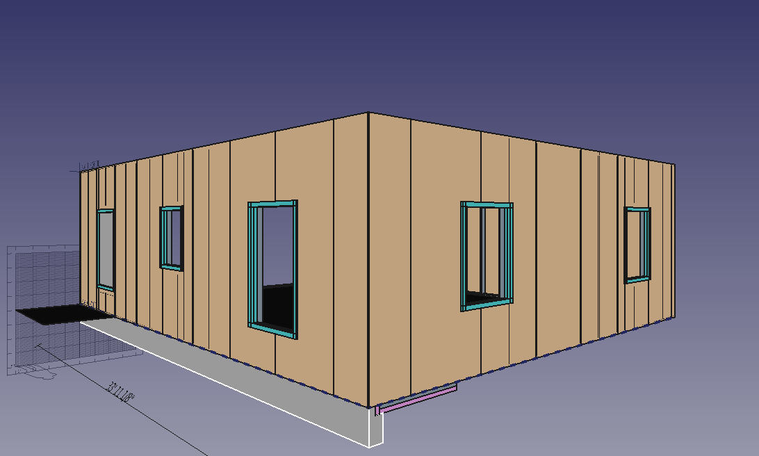
This is a great project!!

About your difficulties with “parametrizing” your structure, the main problem is that there are zillions of ways to do that in FreeCAD. You could start with having a baseline (a draft line for ex.), then subdivide it, then extrude it vertically, then build a sketch on top of it with only the vertical edges, then build other sketches on top of this, then play with 2D offsets and extrusions, etc, etc. But there are many, many other ways too (start with a big rectangle that is your “wall face” for ex.) The quest for the absolute parametric model is endless. The thing is you’ll also lock you in a kind of infernal world where a single hiccup somewhere could create havoc in your whole model.

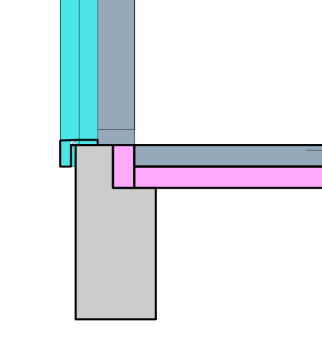
I advise for keeping parametric only what you intend to change over time. For ex, the spacing between the vertical studs. Then, for many parts, it’s often easier/safer to redo or move objects when they need to change than keeping everything automatic. For ex. I very often do myself the openings of walls by subtracting boxes rather than using the window’s automatic hole system. It gives more control, I can turn stuff off independently, etc.

In short, there is no easy answer there… It’s all a matter of “designing” the parametric chain of your model, and more than often you find out that it’s not good in the midl of your work, and you end up redoing some parts…

The easiest way IMHO to do stud walls is using curtain walls, BTW. For the truss, I don’t think it would be so hard either, start with a sketch to define where your different pieces need to be, if you fall on a very simple and regular scheme, use the Arch truss tool, if you have a more complex thing, then draw/model the pieces one by one, and make a compound of it all. Then you’ll have an object that’s easy to clone/link around, and also easy to modify/add/change pieces if needs be…

In any case the exploration you’re doing is very precious as it provides a lot of important info for other users. Keep going!!

if you have a more complex thing, then draw/model the pieces one by one, and make a compound of it all.

Yeah, I think that’s what I’ll do for the trusses. Been a wild few weeks, fired up the latest Freecad 0.19 rev 22366… open up where I left off doing the door previously… and then…

Oof. I can’t select the sheathing panel that I need to cut out the door opening in. It just goes to selecting Default Site when I click it in the view. Strange things ensue…
https://cloud.schwend.us/index.php/s/9ccoJXsYtPB5PK7/download

Basically I can’t seem to interact properly with sheathing panel Panel010. So I can’t cut the door opening. Hrmph. I guess this is why I put it down so many weeks ago.

I have seen this before. The problem is caused by the default site containing a 3D representation of the nested objects. The solution is to delete the site (without deleting its content of course). Alternatively you can change the Selectable property (on the View tab) of the site to false.

Toggling selectability off made it so the site no longer got selected, but I still couldn’t select the panel from the 3d view. Your site-deletion suggestion worked, however.

I’m still unable to use the Subtract tool with an extrusion and a panel… No errors or anything in the report view. I thought this was how I did the holes previously…

You have used the Part_Cut tool. The Arch_Remove tool does not work with panels.

That Selectable property on an Arch Site has proved to be a nasty gotcha! I too got some odd selection results after it it was toggled to False but deletion fixed the issue.

I beg to differ - that’s how I do it all the time - see attached file.

Draw Panel, re-orient upright and re-position to suit. Draw rectangle partially covering panel, extrude it to straddle panel. Select extrusion, Ctrl-select Panel, press Arch Remove. Voila, a cut panel!

Command that was executed from Python Command Console was
Arch.removeComponents([FreeCAD.ActiveDocument.Extrude],FreeCAD.ActiveDocument.Panel)
A0090020PanelCuts001.FCStd (11.7 KB)

You are correct. The question is then: why does it fail for Panel010 in OverkillTASF’s file?

I had a squiz at DuckDuckGo re garage opening portal frames which they seem to be called.

Mr Weyerhauser (a large timber processor in the US), the International Building Code (IRC) and others seem to have some pretty good sketches and notes re these large openings.

A few quick pointers from what I read:
Max opening according to the IRC is 18’. Above that, a timber header cannot withstand the loads and tends toward lateral buckling, ie. the header bows inward or outward toward catastrophic failure. Similarly pony walls above dropped headers cause fixing headaches for downward load paths from the roof over large openings - avoid dropped headers. Attachment of header ends to the king stud(s) at each end to stop header rollover and to transfer load paths down the foundations is ultra-critical.

Continuous garage door opening headers fully extending from over the door opening over an adjacent doorway or window is frowned upon - the compression loads flip to the bottom of such a header, reducing the lateral restraint. It makes the connection from the header underside to the narrow supporting mid-wall section act like a hinge under loads. Bad news for an already heavily loaded beam! Better to have a separate header for each opening, with common centrally located ends each supported by their own king posts. Lateral restraint is then only needed for the header top edge in compression.

It is often needed to have the garage door opening with in-plane structural bracing in the walls adjacent to the left and right ends of such large openings. To do this bracing needs to be in adjacent wall sections each at least 18" wide. This at extreme opening limits of 18’ necessitates a total wall length of upwards of 21’. 6" of wall at each end of a large opening will not cut it.

Plenty of design issues to contemplate there! I’m sure your structural wizard will confirm such requirements for timber portal framing, but going on the info already available out there, I’m sure you could do a credible initial design to incorporate your future garage door.

Will have to look again later today - only quick idea is the selection order correct?

Cheers.

Continuing on…

I see in the latest gitlab version of the house from OKill, there is no cut of Panel010. Looked at previous copies I had downloaded, I’ll admit that I did lose track of which copy is which. Maybe some sort of versioning is required in the filename?

The underlying rectangle for the extrusion seems to be at 90 degrees to the actual Panel010 and is located at the rear of the house/garage we should be cutting something out of. Once re-oriented by 90 deg to be aligned to the panel, re-positioned the rectangle to the intended doorway and then reverse rotated / repositioned the extrusion by 90 degrees an actual cut seems to work on Panel010 using an extrusion and Arch Remove.

Cheers, PMac.

Thanks for your analysis. But this may also be a bug. In the original file the extrusion and the panel intersect. I would think that the Arc_Remove command should then work.