Add angle dimension to hole centres

Hi,

I have problems adding angle dimensions to holes in TechDraw. I just don’t know how it’s done. See the example. There are three holes at different angles („Top“ view, here shown at the bottom).

How to add the angle dimensions? Also I’m confused about the dots displayed for the holes. I expect four (or six) dots to represent the holes. The right hole has only two dots, the middle hole has way too many. Maybe I’m doing something wrong here.

OS: Debian GNU/Linux bullseye/sid (X-Cinnamon/lightdm-xsession)
Word size of OS: 64-bit
Word size of FreeCAD: 64-bit
Version: 0.19.22284 (Git) AppImage
Build type: Release
Branch: master
Hash: bf1e8e48389f5e9e25bd77b67fe98da4213e797c
Python version: 3.8.5
Qt version: 5.12.5
Coin version: 4.0.0
OCC version: 7.4.0
Locale: English/United Kingdom (en_GB)

dimension-hole.FCStd (213 KB)

Hello SIXe

Greetings to the whole community!

Here is the correct technical drawing, attached the FC file revised in the layout.

As you can see, the two technical drawings, one made with another cad3D, have similarities, but the one made with an alternative cad has some peculiarities (more technical) that TechDraw cannot yet do, moreover the speed of execution of the technical drawing with TechDraw has been more slow.

In order to have these peculiarities and be faster it should be integrated with the tools that are specified in this post https://forum.freecadweb.org/viewtopic.php?f=35&t=49719&start=30
other cad3D.png
FreeCad_TechDraw.png
dimension-hole_3.FCStd (60.1 KB)

Would you mind explaining how you have done it?

Hi chrisb,
yes I will do it with pleasure, I need some time to write all the steps step by step … they can be much more useful for beginners

Thanks @domad for taking the time to create the drawing.

That’s exactly what I wanted to achieve, but don’t know how. Especially I’m interested in how you created those centre lines for the holes (in grey). There are no snapping points for those centre lines. Also I don’t know how you created the angle between the holes and the vertical centre line. It can’t be selected to add a dimension.

Hi SIXe,
I’m writing step … step, as I already told chrisb.
I’m not a native English speaker so I need some time to do this. I hope to post it as soon as possible

No pressure. Take your time. Your help is much appreciated. I’m in no rush, just learning and practicing the basics.

Very well!

Liberal application of center lines will help.
dimension-hole_angles.png

Also I’m confused about the dots displayed for the holes. I expect four (or six) dots to represent the holes. The right hole has only two dots, the middle hole has way too many. Maybe I’m doing something wrong here.

It isn’t you. It is a problem in OCC. Use the perspective projector with a long focus length. It will often produce a better projection that the orthogonal projector.
dimension-hole_angles.FCStd (215 KB)

Sort-of. What I’ve tried:

  • Horiz Center Line: True
  • Vert Center Line: True
  • Perspective: True
  • Focus: 1km

That results in sane snapping points and centre lines. Then I tried adding centre lines for the holes like that:

  • Select the two snapping points for a hole
  • “Add centerline between two points”
  • Aligned: ✓
  • Extended By: 25mm
  • Colour: #7f7f7f

Centre line appears. So far so good.

But it’s not possible to create an angle dimension between the vertical centre line and the newly created hole centre lines. Why? The function “Insert Angle Dimension” does not snap to the vertical centre line. It can’t be selected.

However, if I create another vertical centre line manually it works, though. But then I don’t understand the idea behind the vertical/horizontal centre line option. And manually creating centre lines if TD has a dedicated centre line option feels like a workaround.

So to conclude my problems why I failed to create the drawings: The snapping point bug + the inability to add dimensions to centre lines (which there might be a solution for).

I had opened another thread to clarify the snapping point question: https://forum.freecadweb.org/viewtopic.php?f=35&t=49998 Your workaround fixes the issue. Is there a bug report already for this issue? (You can post the reply in the other thread.)

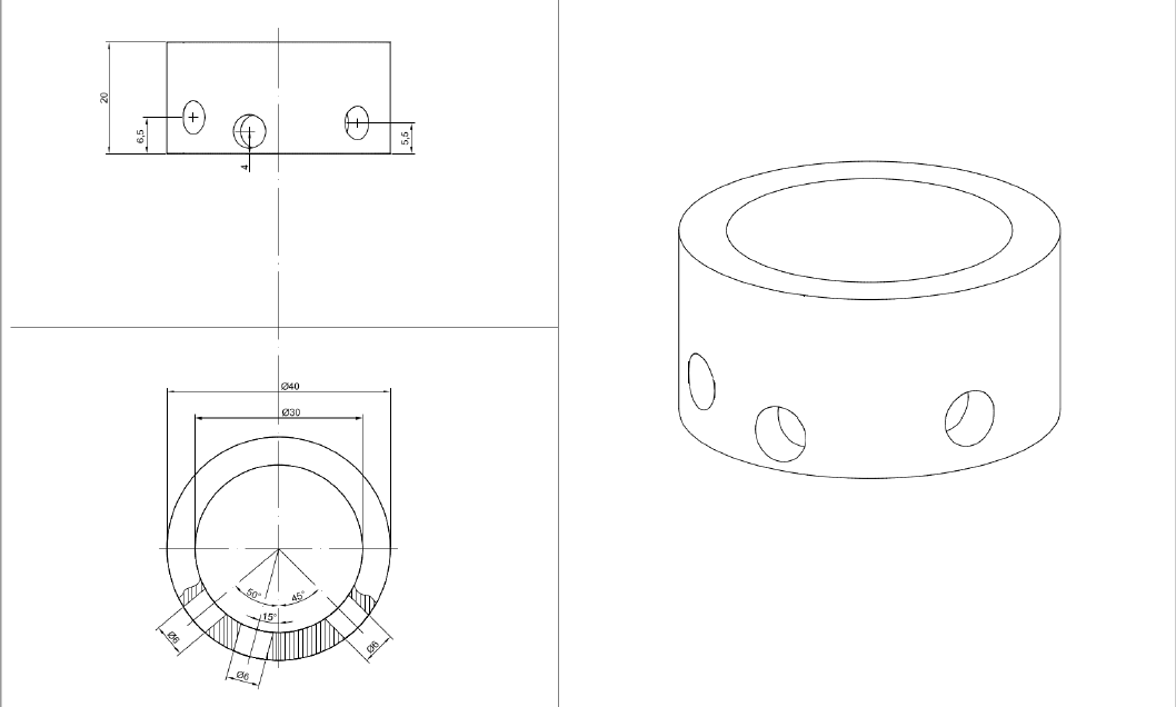
Step-by-step procedure for sizing the drawing

Word size of OS: 64-bit
Word size of FreeCAD: 64-bit
Version: 0.19.22319 (Git)
Build type: Release
Branch: master
Hash: 33ef4e0e35fba74c6e2fa3829cfd15c4b6f67e94
Python version: 3.6.8
Qt version: 5.12.1
Coin version: 4.0.0a
OCC version: 7.3.0
Locale: Italian/Italy (it_IT)

1 - insert new standard drawing, by default it inserts the A4 sheet, to change it → structure → select Template → properties → Data → Template click on the button with 3 dots go to the installation root folder of FreeCad then click → Data → Mod → TechDraw → Templates and choose the one you want.
2 - model view → set the Front view
3 - structure → select object → click → insert view
4 - model view → set top view
5 - structure → select object → click → insert view

we select the views one at a time and set the scale to double
click on the view → properties panel → Data → record Scale = 2.0000

we insert the dimensions in the Front view

to insert the center line of the view we select the view → properties → view → record Vert Center Line = true;

left hole dimension

6 - select the two vertices (upper and lower) of the ellipsoid → enter the cosmetic line through two points;
(in the actions panel we leave everything as it is and click → Ok);

7 - reselect the two vertices of the ellipsoid → enter the two-point central cosmetic line;
in the actions panel we set the options:

  • orientation → horizontal;
  • extended by → 3 mm (or other value);
  • style → at times (or other);
  • click Ok;

8 - we select the cosmetic line of point 7 at the same time (ctrl key) at the vertex at the left base of the object → click enter Vertical dimension (6,50000 mm should appear)

  • to limit the number of digits we select the quota and in the properties panel we modify the value of the “Format spec” record in% .0f (no decimal) or% .1f (one decimal) or other;

8.1 - we repeat the same steps for the other holes;

9 - select the vertices of the left side edge (object height) click → enter Vertical dimension.

P.N.
If any dimension is entered with an incorrect value, we can correct this value on the data properties panel → “Format spec” record, insert the exact value manually and in the “Arbitrary” record → set “true”;

we insert the dimensions in the top view

with regard to the standard dimensions of the diameters, I believe there are no problems, they are quite intuitive to insert;

10 - trace the center lines of the object, select the outer circumference and click on “Insert quadrant cosmetic vertex” → simultaneously select (ctrl button) 2 diametrical (vertical) cosmetic points → insert center line two points, in the actions tab click → horizontal orientation, extended = 4 mm, style = line-dot;
we do the same with the other two diametrical points (horizontal) by choosing vertical orientation and entering the other values equal to those entered before

11 - trace the center line of the hole on the left, select at the same time (ctrl key) the two points that define the diameter placed on the external circumference of the click object → two-point central cosmetic line, in the click actions → aligned , extended = 10 o 12 mm, style = dash-dot → Ok;

11.1 we use the same procedure for the other holes;

12 - we draw the lines of the left hole: since this hole has no references on the inner circumference, we insert two cosmetic vertices on it trying to put them parallel to the center line of the hole and aligned with those existing on the outer circumference, we select the inner circumference click → insert cosmetic vertex, in the actions tab click → Point Picker and define the insertion point on the circumference; we do the same for the insertion of the other cosmetic point;

13 - draw the dotted lines at the edge of the hole: select at the same time (ctrl key) the cosmetic vertex of the outer circumference and the aligned one (which we created) placed on the inner circumference → click insert cosmetic line two points and in the actions tab click Ok;
we do the same with the other two points;

14 - since the other two holes have the references on both circumferences, we trace the cosmetic lines in strokes that define the holes geometrically, the procedure is the same as in point 13;

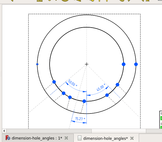
now we are ready to indicate the angular dimensions of the direction of the holes

15 - we section the vertical centerline of the object and at the same time (ctrl key) the inclined one of the left hole click → enter angle dimension (it should appear 50,0000 °) in the properties tab → Data → record Format spec =% .2f now the value is 50.00 ° or % .0f for the value 50 °;

16 - we do the same to indicate the other angular dimensions of the other holes;

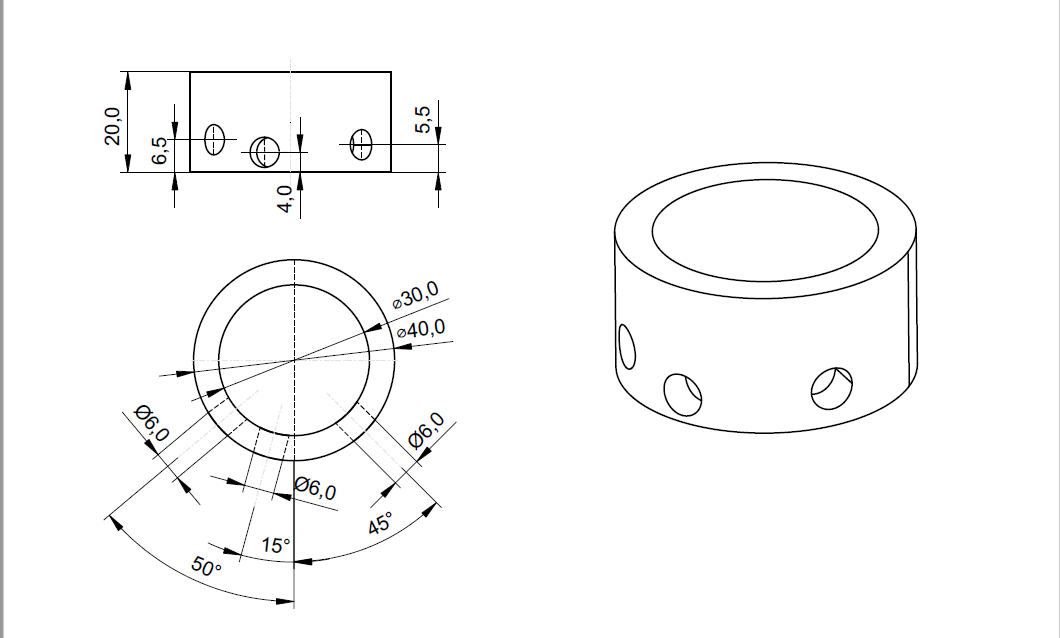
we indicate the size of the hole diameter with the conforming symbol (⌀)

17 - hole on the left, select at the same time (ctrl key) the vertices placed on the outer circumference → enter dimension length aligned, in the property sheet → Data → record Format spec = ⌀% .2f (copying the symbol ⌀ from the word wrinter and then pasted), now the dimension value is ⌀6.00 or with ⌀% .0f it becomes ⌀6;

18 - we do the same to indicate the other dimensions of the holes;

19 - we can now indicate the other dimensions that interest us the external and internal diameter of the object (⌀40 and ⌀30) with the appropriate function insert dimension diameter;

20 - if we want we can insert the 3D axonometric view and eventually define notations and other useful things for the construction of the object.

I hope my English translation is clear and understandable.

If any step is doubtful, you can ask for clarification
As you have experienced, the steps are many, slow and not very intuitive, (think how long it would take for a very complex drawing and how many cosmetic points should be inserted without considering the low precision) I therefore believe, turning to the developers, that the Draft tools should be extended in TechDraw but above all the snaps tools.

Happy Sunday to the whole community!

It would be nice if “Centerline between two points” had a fourth option for the orientation: Through both points. It can be done by a leader line, but that may have a different layout.
Perhaps that option could even replace the leader line.

Hi chrisb, nice to hear from you.
I don’t want controversy with anyone. But I remain of my idea.
We can invent everything, but what’s the point of inventing other tools if FC already has very flexible and powerful tools like Draft with Snaps:

  • wouldn’t it be more logical to extend these tools in TechDraw?
  • why were Draft and Snaps included in Arch and BIM and no other tools were invented?
  • how can you not notice the sizing power that is already in FC with the “Create a dimension” Draft tool that uses snaps to indicate the points?
    An expert in CAD / 3D design and a great user of FreeCad wrote: … .. I well remember the “limiting” feeling I feel in using TechDraw … they are relatively simple drawings, but in this simplicity I feel those “disarming boundaries” …!
    Still good Sunday

To integrate such tools is probably much more difficult than offering a fourth option to centerline.

No Crisb, for one simple reason:
TechDraw is the only workbench that must produce all kinds of documents:

  • civil engineering drawings
  • technical drawings of building engineering
  • architectural technical drawings
  • mechanical engineering drawings
  • structural engineering drawings
  • technical drawings of naval engineering
  • aeroneutic and space engineering technical drawings
  • electrical engineering drawings
  • technical drawings of hydraulic engineering
  • hydraulic drawings (circuits and components in 3D and 2D blocks)
  • pneumatic technical drawings (circuits and components in 3D and 2D blocks)
  • technical drawings of digitized pneumatics (fluid dynamics)
  • thermodynamic technical drawings
  • technical drawings for BIM
  • etc.

I don’t continue because I would risk not including many others.
By this I mean that “TecHDraw” must become a universal workbench (it must “know how to speak many languages”) it is unthinkable to do a “TechDraw” for each of these specialties since each of these has its own specific legislation for the production of technical drawings, therefore, by inserting these two extensions, “TechDraw” becomes as if by magic “heterogeneous” allowing you to adapt to any request of FC Workbenchs and avoiding the forced use of other software.

I know very well that it is damn complicated to make it but if the developers don’t start it will always remain complicated (I know how punch card computers were programmed, I know sequential tape processors, I know 5 1/4 “paper” floppies ", I was already drawing with the “multiplan” using the edges of the cells and without the use of the mouse, etc … I have witnessed all the computer evolution)

Believe me it is necessary to start this great challenge.

First of all, thank you so much for this detailed how-to. I tried to follow it step by step and will describe my results as follows. Some steps I couldn’t reproduce.


This results in:

CenterLineBuilder - endpoints are equal
CenterLineBuilder - check V/H/A and/or Flip parameters

I could not get this to work. Maybe this is my fault and I’m doing something wrong.

8 - I’ve changed the default “Format Spec” in Edit → Preferences → TechDraw → Advanced → Dimension Format, so I don’t have to mess with it every time. Only for diameters and other outliers.

10 - I’ve used View → Vert/Hor Center Line which surprisingly doesn’t work here. This was one of my main mistakes. I don’t know why centre lines have to be added manually if TC has a function to automatically add them. But apparently it doesn’t work the way I think it does. This was one of the main culprits why my attempts failed.

11 - A bug in OOC makes this very hard for the middle hole and impossible for the right one because the snap points are missing. See https://forum.freecadweb.org/viewtopic.php?f=35&t=49998.

Then I tried using wandererfan’s workaround (https://forum.freecadweb.org/viewtopic.php?f=35&t=49976#p428649), which resulted in a segfault:

Program received signal SIGSEGV, Segmentation fault.
#0  /lib/x86_64-linux-gnu/libc.so.6(+0x3be30) [0x7f1fd366ce30]
#1  0x7f1f642ccd72 in TechDraw::CenterLine::initialize() from /tmp/.mount_FreeCAuhFFqw/usr/lib/TechDraw.so+0x22
#2  0x7f1f642ce0fd in TechDraw::CenterLine::CenterLine(Base::Vector3<double>, Base::Vector3<double>) from /tmp/.mount_FreeCAuhFFqw/usr/lib/TechDraw.so+0x26d
#3  0x7f1f642ce4ee in TechDraw::CenterLine::CenterLineBuilder(TechDraw::DrawViewPart*, std::vector<std::__cxx11::basic_string<char, std::char_traits<char>, std::allocator<char> >, std::allocator<std::__cxx11::basic_string<char, std::char_traits<char>, std::allocator<char> > > >, int, bool) from /tmp/.mount_FreeCAuhFFqw/usr/lib/TechDraw.so+0x2ee
#4  0x7f1f4528cfd7 in TechDrawGui::TaskCenterLine::createCenterLine() from /tmp/.mount_FreeCAuhFFqw/usr/lib/TechDrawGui.so+0x237
#5  0x7f1f4528d436 in TechDrawGui::TaskDlgCenterLine::accept() from /tmp/.mount_FreeCAuhFFqw/usr/lib/TechDrawGui.so+0xa6
#6  0x7f1fd6157709 in Gui::TaskView::TaskView::accept() from /tmp/.mount_FreeCAuhFFqw/usr/bin/../lib/libFreeCADGui.so+0x59
#7  0x7f1fd3b677b8 in QMetaObject::activate(QObject*, int, int, void**) from /tmp/.mount_FreeCAuhFFqw/usr/bin/../lib/libQt5Core.so.5+0x780
#8  /tmp/.mount_FreeCAuhFFqw/usr/bin/../lib/libQt5Widgets.so.5(+0x274bb1) [0x7f1fd447abb1]
#9  0x7f1fd3b677b8 in QMetaObject::activate(QObject*, int, int, void**) from /tmp/.mount_FreeCAuhFFqw/usr/bin/../lib/libQt5Core.so.5+0x780
#10  0x7f1fd44131fe in QAbstractButton::clicked(bool) from /tmp/.mount_FreeCAuhFFqw/usr/bin/../lib/libQt5Widgets.so.5+0x32
#11  /tmp/.mount_FreeCAuhFFqw/usr/bin/../lib/libQt5Widgets.so.5(+0x20d8b7) [0x7f1fd44138b7]
#12  /tmp/.mount_FreeCAuhFFqw/usr/bin/../lib/libQt5Widgets.so.5(+0x20e14c) [0x7f1fd441414c]
#13  0x7f1fd44141e8 in QAbstractButton::mouseReleaseEvent(QMouseEvent*) from /tmp/.mount_FreeCAuhFFqw/usr/bin/../lib/libQt5Widgets.so.5+0x88
#14  0x7f1fd43a5c3e in QWidget::event(QEvent*) from /tmp/.mount_FreeCAuhFFqw/usr/bin/../lib/libQt5Widgets.so.5+0xce
#15  0x7f1fd437a82a in QApplicationPrivate::notify_helper(QObject*, QEvent*) from /tmp/.mount_FreeCAuhFFqw/usr/bin/../lib/libQt5Widgets.so.5+0xde
#16  0x7f1fd437f095 in QApplication::notify(QObject*, QEvent*) from /tmp/.mount_FreeCAuhFFqw/usr/bin/../lib/libQt5Widgets.so.5+0x79d
#17  0x7f1fd5e8cab9 in Gui::GUIApplication::notify(QObject*, QEvent*) from /tmp/.mount_FreeCAuhFFqw/usr/bin/../lib/libFreeCADGui.so+0x89
#18  0x7f1fd3b51186 in QCoreApplication::notifyInternal2(QObject*, QEvent*) from /tmp/.mount_FreeCAuhFFqw/usr/bin/../lib/libQt5Core.so.5+0x88
#19  0x7f1fd437e53f in QApplicationPrivate::sendMouseEvent(QWidget*, QMouseEvent*, QWidget*, QWidget*, QWidget**, QPointer<QWidget>&, bool, bool) from /tmp/.mount_FreeCAuhFFqw/usr/bin/../lib/libQt5Widgets.so.5+0x283
#20  /tmp/.mount_FreeCAuhFFqw/usr/bin/../lib/libQt5Widgets.so.5(+0x1af554) [0x7f1fd43b5554]
#21  /tmp/.mount_FreeCAuhFFqw/usr/bin/../lib/libQt5Widgets.so.5(+0x1b03a6) [0x7f1fd43b63a6]
#22  0x7f1fd437a82a in QApplicationPrivate::notify_helper(QObject*, QEvent*) from /tmp/.mount_FreeCAuhFFqw/usr/bin/../lib/libQt5Widgets.so.5+0xde
#23  0x7f1fd43803f1 in QApplication::notify(QObject*, QEvent*) from /tmp/.mount_FreeCAuhFFqw/usr/bin/../lib/libQt5Widgets.so.5+0x1af9
#24  0x7f1fd5e8cab9 in Gui::GUIApplication::notify(QObject*, QEvent*) from /tmp/.mount_FreeCAuhFFqw/usr/bin/../lib/libFreeCADGui.so+0x89
#25  0x7f1fd3b51186 in QCoreApplication::notifyInternal2(QObject*, QEvent*) from /tmp/.mount_FreeCAuhFFqw/usr/bin/../lib/libQt5Core.so.5+0x88
#26  0x7f1fd3ef740b in QGuiApplicationPrivate::processMouseEvent(QWindowSystemInterfacePrivate::MouseEvent*) from /tmp/.mount_FreeCAuhFFqw/usr/bin/../lib/libQt5Gui.so.5+0x6d3
#27  0x7f1fd3ef7ff7 in QGuiApplicationPrivate::processWindowSystemEvent(QWindowSystemInterfacePrivate::WindowSystemEvent*) from /tmp/.mount_FreeCAuhFFqw/usr/bin/../lib/libQt5Gui.so.5+0x175
#28  0x7f1fd3ee4dd4 in QWindowSystemInterface::sendWindowSystemEvents(QFlags<QEventLoop::ProcessEventsFlag>) from /tmp/.mount_FreeCAuhFFqw/usr/bin/../lib/libQt5Gui.so.5+0x64
#29  /tmp/.mount_FreeCAuhFFqw/usr/plugins/platforms/../../lib/libQt5XcbQpa.so.5(+0x5af0e) [0x7f1fcfa60f0e]
#30  /tmp/.mount_FreeCAuhFFqw/usr/bin/../lib/./libglib-2.0.so.0(g_main_context_dispatch+0x2cb) [0x7f1fd0c19b3b]
#31  /tmp/.mount_FreeCAuhFFqw/usr/bin/../lib/./libglib-2.0.so.0(+0x54d81) [0x7f1fd0c19d81]
#32  /tmp/.mount_FreeCAuhFFqw/usr/bin/../lib/./libglib-2.0.so.0(g_main_context_iteration+0x2e) [0x7f1fd0c19e0e]
#33  0x7f1fd3b8042b in QEventDispatcherGlib::processEvents(QFlags<QEventLoop::ProcessEventsFlag>) from /tmp/.mount_FreeCAuhFFqw/usr/bin/../lib/libQt5Core.so.5+0x63
#34  0x7f1fd3b4dbc1 in QEventLoop::exec(QFlags<QEventLoop::ProcessEventsFlag>) from /tmp/.mount_FreeCAuhFFqw/usr/bin/../lib/libQt5Core.so.5+0x187
#35  0x7f1fd3b51a39 in QCoreApplication::exec() from /tmp/.mount_FreeCAuhFFqw/usr/bin/../lib/libQt5Core.so.5+0x105
#36  0x7f1fd5e04ca2 in Gui::Application::runApplication() from /tmp/.mount_FreeCAuhFFqw/usr/bin/../lib/libFreeCADGui.so+0x15a2
#37  /tmp/.mount_FreeCAuhFFqw/usr/bin/freecad(+0x37cd) [0x55aa901f37cd]
#38  /lib/x86_64-linux-gnu/libc.so.6(__libc_start_main+0xea) [0x7f1fd3657cca]
#39  /tmp/.mount_FreeCAuhFFqw/usr/bin/freecad(+0x4521) [0x55aa901f4521]

I started all over, and it worked without segfault. So I cannot reproduce the segfault and from now on I’m using the workaround.

Maybe the bug results in different glitches on your machine than mine. Or you’re not affected at all. Dunno.

12 - I don’t quite understand. You write “since this hole has no references on the inner circumference”. But it does: the hole has two vertices, snap points on the inner circumference. The references on the outer circumference however are missing. Either I’m misunderstanding you or maybe it was just a typo (inner/outer).

New Cosmetic Vertex → Point Picker doesn’t allow to snap to the correct position. It’s only possible to select some random point with no relation to the part. I instead used the inner snap points, resulting in straight lines (from the dimension) rather than dotted lines. Alternatively one could maybe display the hidden lines (also more of a workaround).

I was not able to solve this.

14 - Maybe this is related to the bug, I’m working with wandererfan’s workaround using “Perspective: True” and then there are only snap points on the inner circumference. So I see no way to (precisely) place those points.

I was not able to solve this.

15 - TD displays an angle of 130° rather than 50° no matter what I try. This is not incorrect, but not what I’m after. Maybe I’m doing something wrong here.

I was not able to solve this.


Thank you again for the detailed description. Frankly, that’s quite a convoluted process as you have already indicated, even for a very simple drawing as this one. And in the end I couldn’t get it exactly the way I wanted (as indicated above). It’s a mixture of i) bugs in FC/TD/OOC and ii) my inability to use the program correctly, I presume.

If you (or someone else) has solution for the issues I wasn’t able to solve, suggestions/solutions are welcome. Steps I couldn’t solve:

  • 6
  • 12/14
  • 15


Good evening to the whole community!
Here is the first sequence … creation of center lines and left hole height dimension
dim_cent_f_sx2.gif

Thanks, I misread your instructions and used “Add a Centerline between 2 Points” rather than “Add Cosmetic Line Through 2 Points”. My fault. It works now.

Good evening to the whole community!
Here is the second sequence … creation of the centerline of the holes, definition of the geometry of the holes, angle dimensioning of the drilling direction and diameter of the holes in the top view.
Good vision…
dim_cent_ang_f_sx.gif

Hello everybody
I think what Domad says makes sense… The max respect for Chrisb from which I cannot count how many posts I have read about him, so thanks, I would like to add that he is usually very wise, a great example is trying to merge assembly developers.

But in techdraw I think domad is right, now by eliminating the “implementation difficulty” factor and thinking only about the goal, I can’t imagine anything more natural than using the powerful draft snaps in techdraw and maybe even the draft tools.
It is possible to do it differently, perhaps easier to develop, but it seems unnatural and requires the user to learn new things.

Just a thought if you are going on the right way with the techdraw… no controversy for me either, it just wants to be a constructive speech.
I think I have described a thought/feeling that an average FreeCAD user will feel when starting with techdraw.

Personally sometimes I don’t even find the time to follow an interesting topic, so for my part only many thanks to the developers… Thanks
Sorry my but English