Hi Guys,
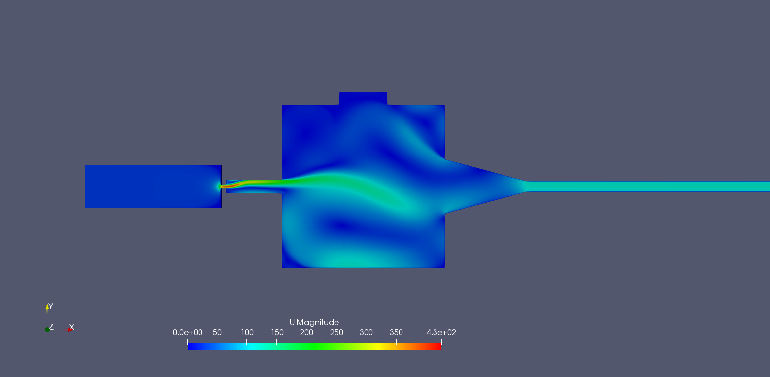
I simulate the nozzle from an abrasive water cutting system. For me, the speed distribution and the pressure distribution is important. There is a pressure of 1000 bar at the inlet (28 m/s velocity, 2.3 * 10 ^ -4 m^3/s volumetric flow rate). Inlet 1 is only one hole at which ambient pressure is present (defined as “open”). The outlet is the small diameter at the end (outlet). When I compare my simulation to reality, the results don’t match. Theoretically, the water jet has to “shoot” through the nozzle because the pressure and speed are high and a negative pressure forms in the mixing chamber. My jet always swirls in the mixing chamber, which shouldn’t be. Can anyone help me further? I tried laminar and turbulent flow, the result was the same for both.
for example:
inlet: 28 m/s
inlet1: open (ambient pressure)
outlet: static prssure
in the picture: red arrow (reality) , black arrow (simulation)
File with mesh: https://www.dropbox.com/s/apl97dwndqxv9te/2D_Test_Velocity.FCStd?dl=0
Can you set the smallest cross-section from Pos1 to Pos2?
Smallest cross-section at Pos1 induces turbulence.
As Johnwang said: close the other inlet for a control-run.
Theoretically…
I played with the parameters:
Closed Inlet 2. Changing viscosity, inlet speed, mesh-refinement.
But no chance, the jet does not “shoot” through the chamber.
Is this an observed effect or a speculation?
There are 4 size of pipes from left to right before the nozzle. You can shoot from Size 1 pipe into Size 2 pipe. From Size 2 pipe to size 3 pipe, you lost a bit velocity. Form 3 to 4, lost more. Though pressure is build up in pipe 4 (the mix chamber), but pipe 1 is just too small to power it up to shoot through the nozzle.
Is it even reasonable to expect acurate results from a single phase simulation of a two phase real life situation? was this not discussed in another topic were multiphase was already suggested?
For those still doubting the water jet creates air entrainment. By taking the air with it through the focusing tube, it depletes the air in the intake chamber. Therefore it creates a depression, sucking air from the air inlet.
The simulation does not reflect reality, because under such conditions there will be cavitation. This type of simulation will create pressures below absolute zero in the nozzle, which can not happen in reality. Just have a look at the pressure. So there should also be water vapor in some parts of the mixing chamber. Openfoam has a solver for cavitating flow. You could give it a try, but you need to set up a case directly in openfoam. Another question is the influence of gravity and air intake as others already said.
OK.
But how to setup the interfoam solver for extreme conditions?
How to simulate the (supersmall) bubbles?
Aaah… there must be an idea to get this problem…
Why Not just simulate the mix chamber + nozzle. Whole left wall as inlet to see what the flow Field looks like. If there is the jet you want, then add a inlet part, say half size of the mix chamber wall. When you understand what a jet needs, then you can open the top air inlet, to test two phase problem. Then add sand.