Dear All,
I really do not know how to proceed. I am following a tutorial on youtube on how to use the arch. In this tutorial there is created first a slab an then on top of the slab a multiple points line. I design the line in the sketcher, after I turn back to arch, select the mulitline and create a wall. I see the wall created in the comboview, but on the 3d view there is no wall to see.
The first time I tried it out it worked, now it does not work any more. what could I have done wrong ?
Thank you very much for any help
Yours,
Erich
Hello Erich,
Could you post some image or the file you are working on, it would be easier to understand the problem this way ![]()
thank you very much, I would like to attach the file I am working on, but how ? Pls excuse, but as you see I am new on this forum, ..
slab.FCStd (8.84 KB)
I think I found how to attach the file.
I now tried to add another sketch to this slab.
I can reproduce it and send the resulting file …
Moved to Arch forum.
You may also attach images for better attraction for discussion ![]()
Example Workflow:-
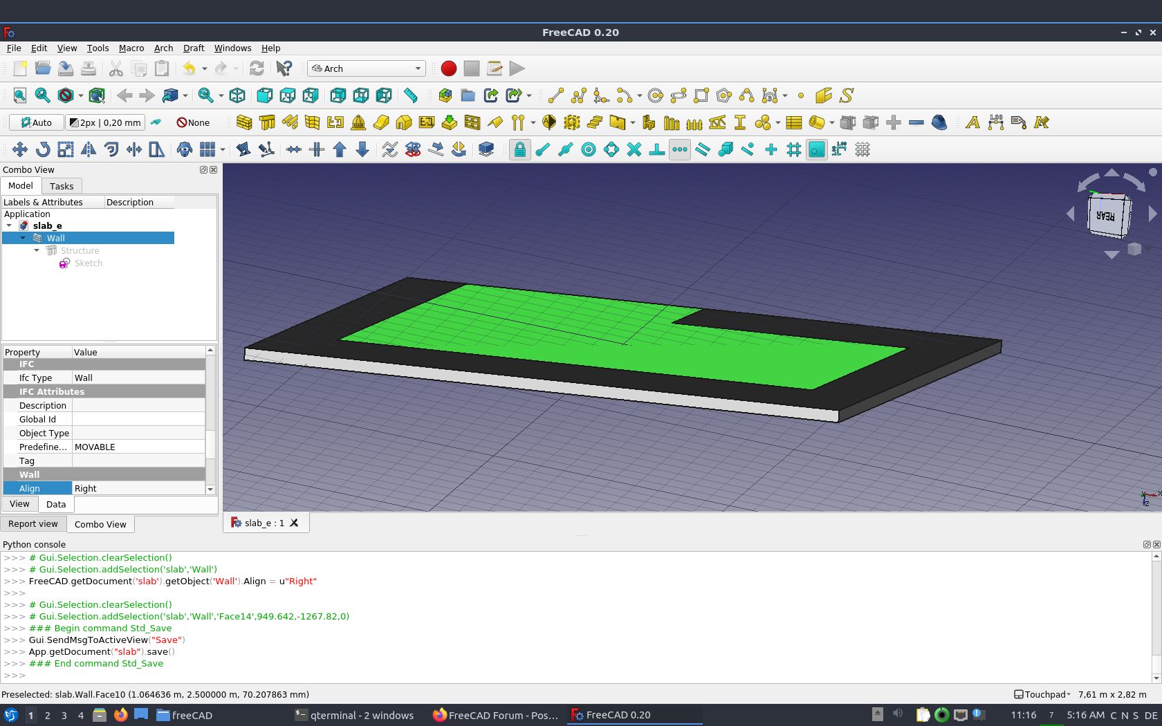
- You may also (re-)use the Same Sketch and Click Arch Wall to build the enclosure
- Find Align in the Wall properties and select ‘Right’ so the Wall build ‘outside’ the Slab
- You may also set Normal in Structure to (0,0,-1) make it extrude ‘downward’ to avoid clash with walls
- Then you may draw another Sketch to represent the internal layout
(Special Remark : There are others who do not use Sketch but Simple Draft Lines /Wire to build Wall) - Select the Sketch / Draft Wires / Lines and Click ArchWall …
slab_ r.FCStd (23.6 KB)


Thank you very much. Tried to add the wall to the same sketch, what I produce is however different from what you have constructed.
The hierarchy is quite different, What did I so wrong ?
A very big thank you
Erich
BTW: in my opinion for this great product would be very useful to have a tutorial let’s call it: “Architecture for Idiots” just to lower the learning curve. I would volunteer to write low level instructions how to build a room, based on my experience … The tutorial which I think is high quality is to high level for newbies …
slab_e.FCStd (15 KB)
Select the Sketch instead of selecting the Structure, then click Arch Wall.
There are quite some youtube video e.g. search Regis on FreeCAD introduction. And there is OSArch … see if I can find the link…
And Wiki and Video by the core developer of FreeCAD and Arch/BIM Workbench @Yorik
https://wiki.freecadweb.org/BIM_ingame_tutorial
https://www.youtube.com/watch?v=rkWOFQ2fGZQ
https://www.youtube.com/watch?v=rkWOFQ2fGZQ
Interesting - I haven’t used a ‘complex sketch’ as Base of a Structure as you do now, it still use the outermost outline to produce a solid ![]()
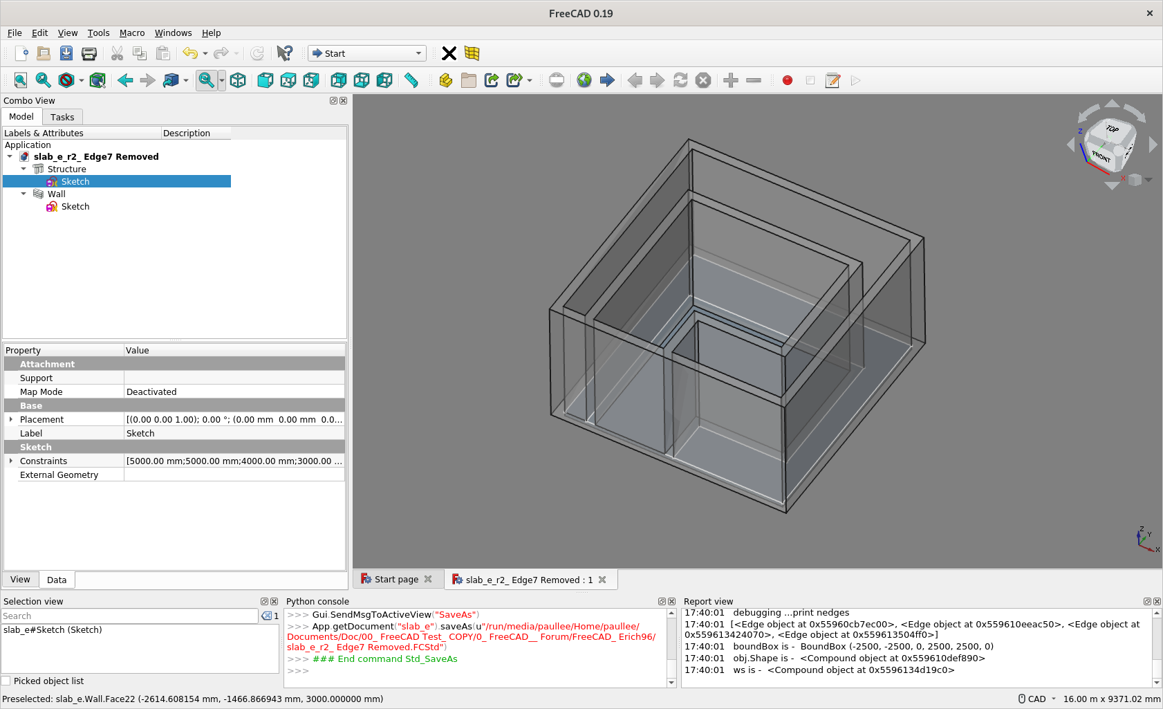
But you have Edge3 overlapped with Edge7 in the Sketch, that practice may produce unpredictable effect - The use of ‘Complex Sketch’ as Base of Arch Wall required more attention / care, so it seems most peoples do not use this workflow ![]()
You may want to remove Edge7 to see if you layout still works.
slab_e_r.FCStd (20.4 KB)
slab_e_r2_ Edge7 Removed.FCStd (19.1 KB)


I just notice that the “Face Maker” option has an impact here. F.e. the aptly named “Cheese” face maker will create holes.
The two wall at the edge of the slab was pure case. It happened as I setup the length of the vertical wall.
I did not know, that I have a complex scatch.
When I select the sketch and make Arch Wall the slab gets a wall, not the wire inside the slab. There is something wrong with my slab I think.
In order to make a plan of the room, (it want to design an entire appartment, therefore further rooms, once I am able to do it) how do you recommend me to proceed ?
Build a slab and add one sketch for every room ?
Thank you very much
Yours,
Erich
Yes, it does, so if there is a close wire within a close wire, you can make a void, e.g. for staircase, or a atrium ![]()
Just in this case the 2 loops touch at one edge …
That seems ok, maybe you post your screencapture / your model for avoidance of doubt what you are facing ![]()
This is more or less most people’s workflow as illustrated in several @yorik’s tutorial / video.
Or you have any problem understanding my posted model ?
The position of the grid seems also strange to me. the first screenshot is front view, the second top view.
Should this not be normal, I have no idea how I achieved it …

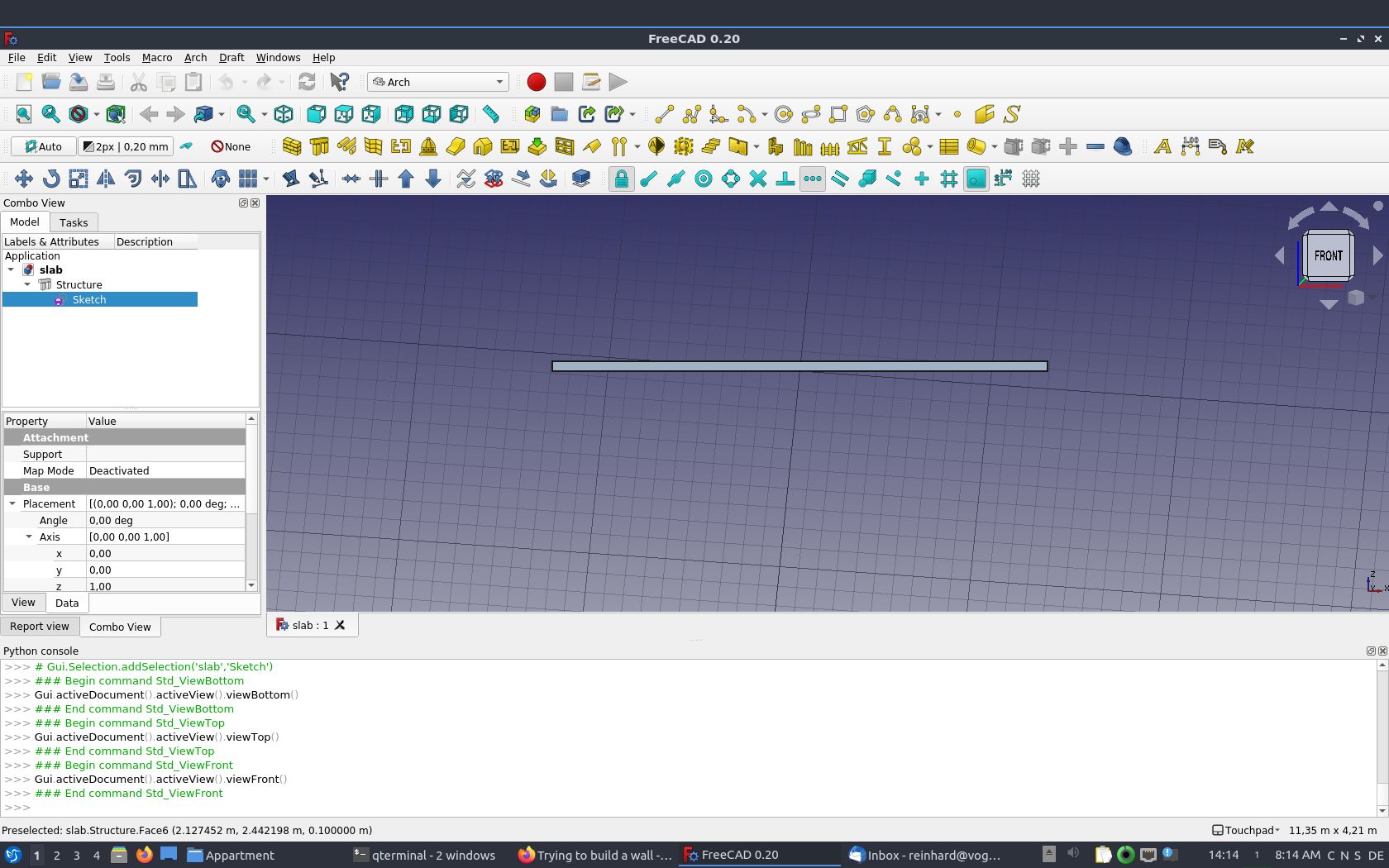
It doesn’t matter for your case at the moment. The grid represent the Working Plane - Check the Draft Workbench Wiki.
There is a button to the left side of your screen with ‘Auto’ shown - which mean the alignment of the Working Plane is automatically set to e.g. align to your view.
Click it, select Top/XY (not sure as not at FreeCAD at the moment) to force it align to plan view. Then, you draw a Draft Line and they will fall on XY Working Plane.
Hello Erich96,
if you are looking for a workflow to create walls using closed sketches as the wall outlines than maybe this could work for you:
- create a closed sketch

. If there are other geometries you want to use later i.e. for slabs create them as construction geometries

- select the sketch and use the part-extrude command

with the correct wall height to make a solid from the sketch
- select the solid and use the arch-wall command

to turn it into a wall
- afterward you can use the sketcher-carbon copy command

to copy your first sketch
- modify the geometry of the sketch copy. Turn for all parts that aren’t needed for the slab the construction mode on, for all others to on.
- now select the copied sketch an turn it to a structure with the arch.structure command

hope this could be useful for you. Here is your manipulated model:
slab_e_r_wall_with_outlines_from_sketcher.FCStd (27.8 KB)
Cheers
Thank you very much, this is a possibility I will give a try also.
In the meantime I succeeded in creating the wall, wow !!!
The slab had in the structure the property normal with the z value set to 1, this meant that the slab was over the null in the horizontal axis(z), i.e. above the x,y surface. I set it to -1. I did this because I noticed, that in the video tutorial the slab is under the x,y plane seen from frontal view.
Then I changed to the sketcher workbench, choosed the surface (the upper one) I want the sketch to be created and clicked on the button new sketch. Designed the wall and closed the sketch. changed to architecture workbench, choosed the new sketch and pressed the wall button. That was it …
Now I will drink a beer and do the same thing later, in order to verify it’s still working …
I think also the structure is fine like that, If I add a room I can add a sketch, I think.
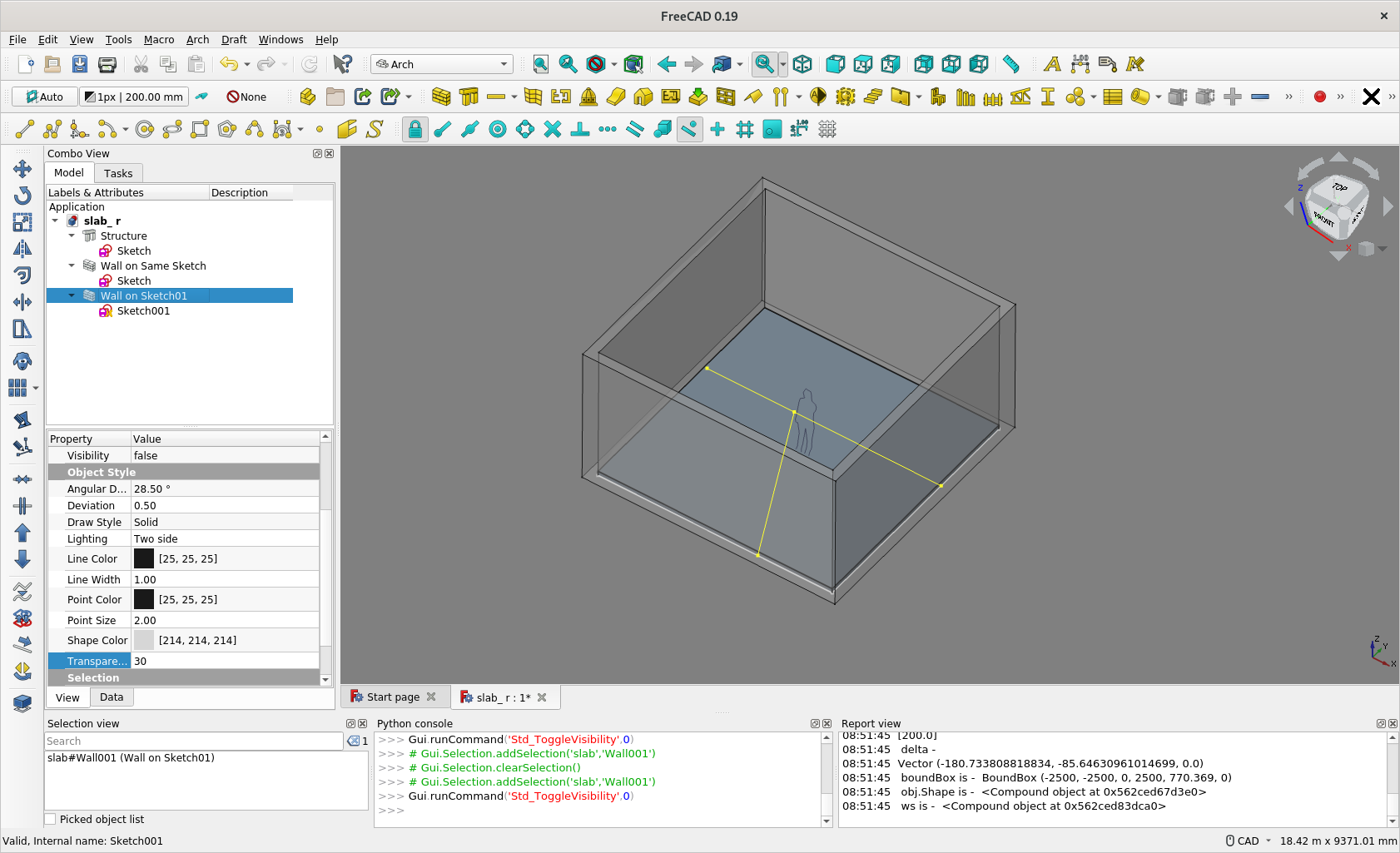
Remaining question for me: how to make the walls transparent as in the examples earlier in this thread from Paullee.
A further question is, if I have more rooms, the common walls, are they shared, or can they belong to one object only,
Thank you very much, now I will try to load a more complex example, I have loaded the data using magicplan on my iphone, this SW can produce data in SVG, DXF and also OBJ format. But the data has to be cleaned.
The attached picture is not nice, but it’s what I wanted …
best regards
Yours, sincerely
Erich

slab_working.FCStd (16 KB)
Congrat ![]()
Just find the Property panel, switch from Data Tab to View Tab. Find Transparency property, try something from 1 to 100.
Not sure fully understand. Just try add an edge in your Sketch001 to ‘divide’ it into 2 ‘rooms’. The ‘divider’ wall are ‘shared’.