For a longer time I was working on a topology optimization script using CalculiX. I have uploaded the project to the GitHub
https://github.com/fandaL/beso
so if someone is interested, you can follow description there and try it. Current state is that I tested it on very simple examples; theoretically it should work also on more complex models, it needs slightly more FEM understanding, more model preparation, and much more computational power. I’m slowly learning programming on this so the quality of the code is corresponding, therefore critical comments are welcomed although I might not be able to correct everything. There is also still a lot of basic stuff to implement and connect to a FreeCAD functionality.
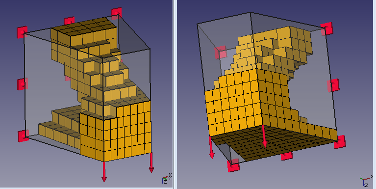
And for picture readers ![]()

Transparent material is initial volume (filled by a mesh) and depicted mesh is final result after removal by algorithm. It is a proposal of material distribution in a lever loaded by the force on the right side, with horizontal fix on the top, and constrained displacement in radial and axial direction on the middle ring (so it can turn around the middle ring centre)
fandaL, you’re my hero!
I never thought I would experience an open source topology optimizer in my lifetime! I’m all cock a-hoop over this!!!
Now I’ve just got a couple of questions; you mention the possibility it uses 1:st order elements for calculations. If so do you think it’s possible in some future to make use of 2:nd order elements? Is this somehow a limitation of Calculix?
Clock cycles: would the calculations run faster if one used a different programming language? Or would it be possible to significantly optimize the code in some way once one get familiar with the code? I’m primarely thinking of code which runs over and over again.
This looks awesome, even 2D and documantation allrady ! Is it an research project ?
FEM on FreeCAD is really growing ![]()
…you mention the possibility it uses 1:st order elements for calculations. If so do you think it’s possible in some future to make use of 2:nd order elements?
At the moment it is possible to use 1st or 2nd order triangle and 1st or 2nd order tetrahedron. Script computes centres of gravity and volume of those elements. At the moment these calculations are with certain inaccuracy for 2nd order elements because there are used the same formulas as for 1st order elements.
Is this somehow a limitation of Calculix?
CalxuliX can calculate volumes (may be I will use them), but I didn’t found CalculiX to output centres of gravity or, even better, position of integration points. I plan to ask someone about integration over an element shape function which could solve these problems.
Clock cycles: would the calculations run faster if one used a different programming language? Or would it be possible to significantly optimize the code in some way once one get familiar with the code? I’m primarely thinking of code which runs over and over again.
Most of the time CalculiX is running a classical FEM analysis in each iteration. Commercial topology optimizers use slightly different method (SIMP), which pure form is better from the mathematical point of view – there is also an educational code available [1], not such a monster in compare to my trials :-]. I decided for BESO method because I found an explanation which I understood better at that time.
Speed of convergence can be controlled by an input parameter “evolutionary_volume_ratio”, but if you set too big value, you get result of poorer quality. Some potential to get it faster is in the more complex method or their combination, I should read more.
Hexaheral or pentahedral mesh have also theirs potential.
Is it an research project ?
Not officially. Partially I worked on it during some school tasks, but it will not be possible later, not in that way, since I already passed all my courses.
ha, awesome, we are really not far behind, since it was just days ago since i have read that autodesk was adding something like this to inventor ![]()
PS: as i understand this is something similar right? not sure since this is not really what i normally work with ![]()
as i understand this is something similar right?
Yes. Same workflow.
In case of sheetmetal part like this, I would prefer shell mesh especially for the rough optimization. Or maybe 3d mesh was on less mouse clicks.
There is another OpenSource topology optimization software available. Just found http://en.z88.de/z88arion/ but did not test it.
BTW: Z88 will be available as solver for FreeCAD FEM soon.
There is another OpenSource topology optimization software available. Just found > http://en.z88.de/z88arion/ > but did not test it.
Seems good. They are farther ![]() , which demotivate me a little bit in continuing my work
, which demotivate me a little bit in continuing my work ![]() . I should reevaluate my motivation.
. I should reevaluate my motivation.
I have written my own optimizer which is open source. (in python)
In this case i use calculiX for solving the physical equation.
You can optimize any problem and model which run on calculiX.
There are different types of optimization:
Maximize Heat-Exchange.
Maximize Stiffnes.
Multi physic topology optimization. (Solving a problem for heat exchange and stiffnes)
https://github.com/DMST1990/ToOptiX
https://www.youtube.com/watch?v=o17b7C4N1uI
In the new version which is not up to date, you can simulate optimized crash profils.
Hi, welcome to the FreeCAD forum.
It seems good. I put it to my candidate list on which programs to look. ![]()
I like your tool, its easier to use than mine. ![]()
I have added two pdf- files, which maybe can help you implementing the topology optimization (SIMP, BESO etc…)
and understanding the different methods.
https://github.com/DMST1990/ToOptiX
- Masterthesis (German) (hard to read, you can just look at the pictures)
- Introduction (German) (Easy to read, except the equations)
There are some parameter studies which explain the behaviour of the used parameters.
If you need some explenation or some help for implementing sth just ask me.
Thank you.
I have some basics of German, so I think this will be a good motivation to practise.
It will take me some time to go through.
Hi, all.
How integrate that on Freecad ?
And how use it to ?
So, I’m not developper. I’m just a beginner user of Freecad (not beginner on CAO).
I have a personnal project on to developpe on CAO for 3D printing and that’s the fonction I search for it.
I don’t have find the good free tool for me at this time on the web.
(Blender don’t have visual interface i can use for the moment : “my eyes bleed” when I attempt to use it, sorry ![]()
and I don’t have test Z88Arion : I’m affraid to don’t speak german enough but attempt anyway now).
Could you post a complete tutorial of each step (from install to final STL result), plz ?
(for the better tool as possible on Freecad, …if it’s possible ^^)
I think a lot of users (who won’t use crack version of commercial tools and don’t have money to paid it) could be really interesting by have that tool directly on Freecad.
Xcuz for my languages errors, that’s not my born laguage ![]()
Thx a lot for your works ![]()
Sam…
Welcome to FreeCAD.
I deleted your duplicate post and removed your e-mail address. Please read the forum rules in the Help Forum as they will provide you with a lot of useful hints
Hi Sam,
integration to the FreeCAD with gui is still far (it is probable that Z88Aurora* will be sooner translated to English). Some help how to run it is below
- create a special folder for your analysis
- follow tutorial from pdf file https://github.com/fandaL/beso
Currently it is not much comfortable for new users (especially if you are not familiar with python). I run it from external python console, but you can instead of it:
- install python 2.x, associate py files and run it simply by double click from your OS (hard to catch mystakes in input since window closes with error to me)
- it is theoretically possible to run it inside the FreeCAD python console, but changes in the beso_config file might need restart of the FreeCAD. Give this to FreeCAD with your working directory path
my_working_directory = 'd:\\analysis_folder\\'

import os, sys
os.chdir(my_working_directory)
sys.path.append(os.getcwd())
and start by
import beso_main
for next runs it will be enough
reload(beso_main)
Now frd results which you drug and drop from your working directory are rather for inspiration, so when you get “good looking” result you need to model it by some cad and after that export in format for your 3D printer, because resulting mesh is not smooth and I didn’t try to export it e.g. to Blender to apply some smoothing filter.
*EDIT: Z88Arion
Thx for your answers ^^
Bonjour Sam,
CAO (conception assistée par ordinateur) means nothing in English, at least nothing that would be relevant here.
In English, the acronym is CAD (computer-aided design), as in… FreeCAD. ![]()
Support for other element types passed my testing - simple 3D model and 2D (different one) model with edge load. It should be possible use all element types in optimization domain except beam elements. Beam elements can be in the model but not in optimization domain.
What was clearly visible was computation time - for 2nd order elements 4-8 times longer than for 1st order elements for same number of elements. I didn’t focus on differences in quality, but 2D models gave different topology for different element types.

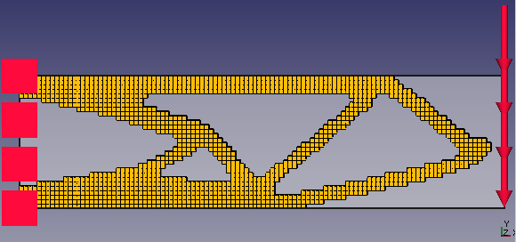


In these cases all was one optimization domain, so edge load on the shell model is “in the air” after process.
Very interesting that different elements give different results, even if you use hundreds of them. Would be interesting what the reason for this is. Mhh neiter nature nor materials does not know femelements. Which one is best ?! It is may be like a path. If the optimizer is on a specific path it just goes this way. There must be academic papers about this.
Mhh and tria3 give a better result than tria6 and quad4 (IMHO) really strange …
That looks very, very interesting!