I have not added any functionality - just coalesced and rearranged what I think is already there.
I think it would make the tool more intuitive: select Profile / select path…select profile /select path,…fiddle with the orientation, etc.
Thanx for your indulgence.
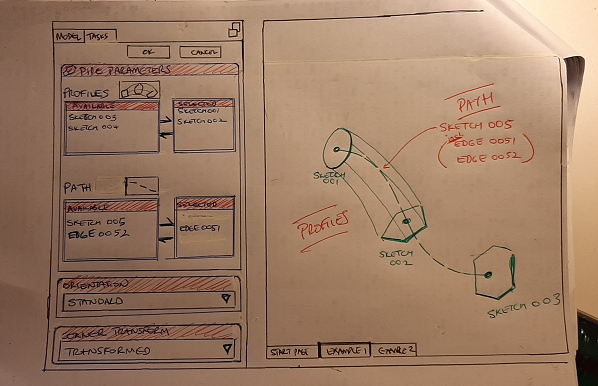
I like your handmade doodle, and I like the selection of the profiles. The Path selection may be more complicated, because the path doesn’t have to be a complete sketch. Parts of sketches or even a selection of edges of a feature are possible - though the latter is not recommended for stability reasons.
On that: if the FC design limitation (as per Help) is that profiles must be orthogonal to paths, then once the primary profile was selected, that would somewhat limit the possible edges that would be valid paths (in addition to the sketches that would be valid paths).
Perhaps once a profile is selected, valid edges on the model could glow green pending selection!
That’s not a limitation, only a recommendation. Where did you find it? See the attached image where the path is neither perpendicular to the sketch plane nor is it intersecting:
I have changed the documentation for the PartDesign tool:
Sketches used for cross-sections must form closed profiles.
The path can only be from a single sketch, feature or ShapeBinder. In case you want to sweep along several sketches, use a (green) SubShapeBinder.
The path must not contain branches or T-junctions etc. Loops are fine.
It is not possible to use a vertex as cross-section.
It can lead to issues if the cross-section is not perpendicular to the path in 3D (some other CAD systems consider the origin of the cross-section as the path and do not require to place that sketch explicitly).
…
The PartDesign AdditivePipe is indeed a sweep very similar to the Part sweep, but there are some significant differences:
PartSweep cannot contain inner loops
The path of a PartSweep can be combined from arbitrary sketches and objects