Okay, fixed in my PathArea branch. It is a silly bug. The orientation may take a while. It is much more complex.
I’ve submit a new fix. Please test the projection as well as the path orientation setting. Now orientation can only be 0=Normal, 1=Reversed, as I mentioned in my previous post.
I have also renamed the original ‘clearance’ parameter in fromShapes to ‘resume_height’ to avoid confusion. Resume height is the relative Z height above the next Z layer height when return from retraction. This can usually be set to step down value. However, Path.fromShapes does not have knowledge of step down, hence you need to manually specify this parameter here. This shall solve your retraction problem.
Results from projects and orientation are looking very good now. No issues to report.
I’m trying to use the projection mode more consistently but there’s something that TechDraw does that I can’t figure out how to do with Path.Area:
With TechDraw, I can select several faces, make a compound, and then get the shapeoutline of the compound. But with Path.Area, I can’t seem to section a single face parallel to the XY plane. I just get an empty projection. Is this possible?
If all the faces are in the same plane, then no need for the expensive projection operation. Just union the face and then remove all inner wires will do. I’ve added a new parameter called ‘Outline’. Set it to true to get what you want.
# union all faces, and then remove all inner wires
area = Path.Area(Outline=true).add([face1, face2, face3])
Part.show(area.getShape())
The difference between ‘Outline’ and ‘Project’ is that ‘Outline’ deals with 2D faces only, while ‘Project’ deals with 3D solid. If the faces are at different plane, then you have to either manually move the faces to the same plane or manually create compound and do section with projection.
Nice! I’ll try it. In my example, the faces were on different planes. I did exactly what you described but always got an empty list when sectioning the compound. I’ll try again and attach a sample file if I get the same results.
My problem with empty section is fixed - I was missing the coplanar check.
Results from outline project using a compound of faces are still showing a bug though.
I’m attaching a file, projectionbug.fcstd.
Cut002 is the original shape.
I selected Face13 and Face14 and ran this test macro:
import Path
import PathScripts.PathUtils as PU
sel = Gui.Selection.getSelectionEx()[0]
obj = sel.Object

profileparams = {'Fill': 1, 'Coplanar' : 0}

c = Part.makeCompound(sel.SubObjects)
r = Path.Area(Project=True).add(c)
r.setPlane(Part.makeCircle(10))

r.setParams(**profileparams)

#env = PU.getEnvelope(c, 10)
#Part.show(r.getShape(-1, True))
sec = r.makeSections(heights=[0.0], project=True)
if len(sec) == 0:
    print ('no section')
    Part.show(r.getShape(-1, True))
else:
    print ('section')
    sec[0].getShape(-1, rebuild=True)

area = Path.Area(Fill=1, Coplanar=0).add(obj.Shape)
area.setPlane(Part.makeCircle(10))
Part.show(area.makeSections(heights=[1.0], project=True)[0].getShape(rebuild=True))
shapeprojection is the overall silhouette of the whole object. It’s perfect.
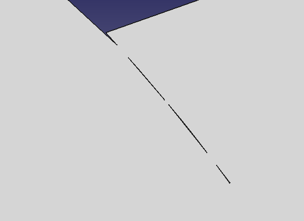
faceprojection is the projection of a compound from the two faces. You’ll see the intersection lines don’t meet correctly.
faceprojectionOutline is the projection with Outline=True. The problem is reduced but still present.
projectionbug.fcstd (102 KB)
I was not clear in my previous post. When I said make a compound, I actually mean to make a compound of face and then extrude a solid. Because makeSection is supposed to only work with solid. I am surprised that you even get any result for face compound. And you have just stumbled upon an unexpected usage of Path.Area.
Here is what actually happened. Section won’t work when there is no solid. So Area just do normal operation on all faces. When you set Coplanar=0, it will not check face plane, and simply convert face wires to 2D by ignore the Z value. That is actually some kind of projection! So, you don’t need to call makeSections at all in this use case. The artifacts you see is due to those faces having some near coincident edges. If you enlarge the shape produced, you’ll see the artifacts are actually small holes. So, by adding Outline=True, you can remove those holes.
After setting Outline=True

So in summary. Here is what you can do to get face outlines
outline = Path.Area(Coplanar=0, Outline=True).add([face1, face2, face3]).getShape()
One more thing, I see lots of getShape(rebuild=True) and getShape(-1, rebuild=True). You normally don’t need to do that. Simple getShape() will do in most cases. And only use getShape(index) to get individual section if you doing section with SectionCount parameter in Path.Area instead of calling makeSections, You almost never need to set rebuild=True, I added that for debugging purpose. You’ll be wasting time to rebuild in most cases.
O.k. Makes sense but those tiny cuts in the second screenshot are still a problem for me. For instance in a path that isn’t offset (for example a laser cutting ‘on the line’ the beam will be spending more time than it should in that corner delivering too much heat. I don’t get those cuts in the TechDraw method. Is that a tolerance thing?
One more thing, I see lots of getShape(rebuild=True) and getShape(-1, rebuild=True). You normally don’t need to do that. Simple getShape() will do in most cases. And only use getShape(index) to get individual section if you doing section with SectionCount parameter in Path.Area instead of calling makeSections, You almost never need to set rebuild=True, I added that for debugging purpose. You’ll be wasting time to rebuild in most cases.
Cool. I started adding the rebuild=True when I was seeing the projection orientation weirdness. I won’t use it in my production code.
If you align those two faces together, you can see the gap.
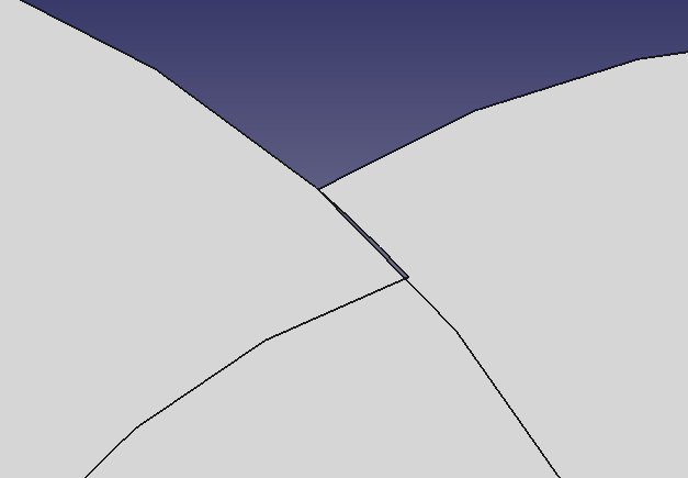
In this cases, you either need to fix the model itself, or you can use the trick to do a slight expansion offset, and then a second shrink offset to remove those gaps.
But, I am curious how TechDraw handles it. Could you please post your TechDraw code?
Huh. That’s weird. It’s not in the model which is just made from stacked and cut cylinders. The gap occurs with the selected faces compounded together. Must be an OCC/tolerance/rounding thing.
Here’s how I call the TechDraw function to generate the perimeter wire from the selected faces.
sel = Gui.Selection.getSelectionEx()[0]
Part.show(TechDraw.findShapeOutline(Part.makeCompound(sel.SubObjects), 1, FreeCAD.Vector(0,0,1)))
I have changed ‘Outline=True’ behavior. It does proper projection now, so that you can throw in any type of faces (non-workplane-parallel, non-planar, etc) and still get correct result. makeSections() now uses the same code to get projection. The ‘project’ parameter in makeSections, or ‘Project’ parameter in Path.Area, is independent with ‘Outline’ parameter in Path.Area. More specifically, ‘project’ or ‘Project’ controls whether you get sliced section, or projected outline sections, and is only effective when you have solid and trying to make section. ‘Outline’ will have effect if you are not making sections. So by simply setting ‘Outline’ to True, you’ll get a single outline face at the work plane.
I’ve also somewhat fixed the artifacts problem. The actual cause of this problem is that, previously, projection is done separately on each shape faces. So two faces are projected separately, and then unioned together, causing rounding error. I’ve fixed that. Now, as long as the two faces are in the same shape/compound, it will be projected together. Faces not in the same compound are still projected separately, because you may add shapes for different operations, like cut, intersect, etc.
In summary, this will give you the correct result without artifacts
shape = Path.Area(Outline=True).add(Part.makeCompound([face1,face2,face3])).getShape()
Part.show(shape)
I’ve also fixed a work plane direction problem. For some shapes, like the Cut shape in your file, all faces have reversed OCC orientation for some reason. This causes the auto selected work plane having the wrong normal (0,0,-1), and in turn, causes section error (i.e. wrong section direction, which means setting SectionCount=-1 will give you only one section). I’ve now forced the normal to point toward the positive axis direction if the selected plane aligns with X, Y or Z plane. This direction problem may also cause projection failure if your manually set a work plane with (0,0,1) direction. It has also been fixed. Please try it out.
If I get a reference to the lower face in the model (Face14) and do
shape = Path.Area(Outline=True).add(sub).getShape() it works as you describe.
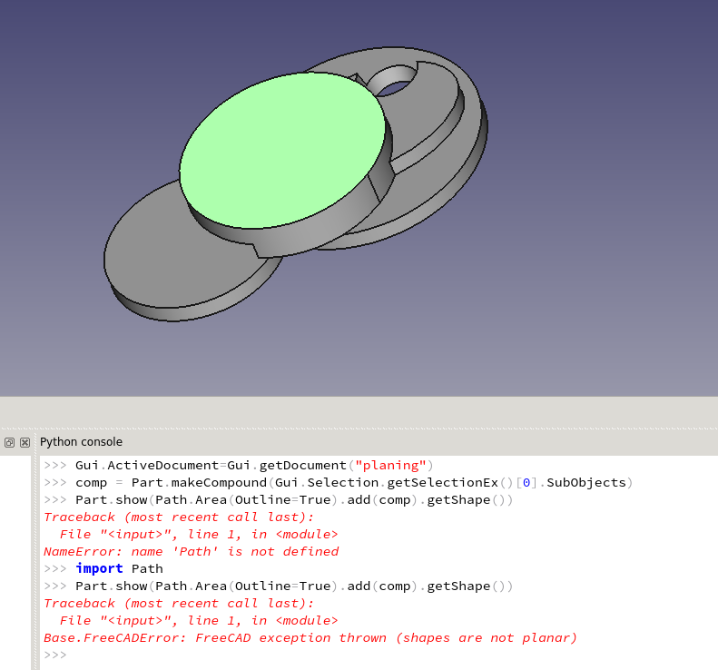
But if I get a reference to the top face (Face13) and do the same thing, I get an error that the face is not planar. However,
DraftGeomUtils.isPlanar(sub) returns True for the same face.
Interestingly, if I select both Face13 and Face14, it works.
Could you please show me your exact code? I just tried it and it works. Are you sure you have pulled my latest commit?
comp = Part.makeCompound(Gui.Selection.getSelectionEx()[0].SubObjects)
Part.show(Path.Area(Outline=True).add(comp).getShape())
My code is effectively the same as yours. I double checked and I’ve merged your branch as of: 56a3501
Running your code snippet, I get the error.
The rest of my FreeCAD info
OS: Linux Mint 18 Sarah
Word size of OS: 64-bit
Word size of FreeCAD: 64-bit
Version: 0.17.11043 +22 (Git)
Build type: Unknown
Branch: feature/PathAreaOps
Hash: 58f106023066cbfbafbe43432b242981a7dee6dc
Python version: 2.7.12
Qt version: 4.8.7
Coin version: 4.0.0a
OCC version: 6.8.0.oce-0.17
Could you please try with OpenCascade official version. That’s the only difference I can tell. I am building with OCE right now. Anyway, I think FC 0.17 is moving to OCCT 7, so you might as well switch to the official library now.
Yes, that did it. Resuming my testing… So far, looks good. ![]()
Yes, it is OCE problem. And I’ve just fixed it. Please try. I’d still strongly suggest you to switch to OCCT 7. It has improved on a lot of other things.
confirmed fixed with occ 6.8.
I’m just about done with re-working the PathMillFace and PathContour operations to use Path.Area exclusively. I’m sure I’ve got plenty of bugs but I’d like to have people test my branch. Unless you’ve got more coming for Area, how about merging your current stuff to master?
Sure, PR submitted.
Offset seems to be giving me 2X what I expect. What am I doing wrong here?
I would expect the boundbox to be 15 ( 2 * 2.5 + 10) but it returning 20.
import Path
import Part

partshape = Part.makeBox(10,10,10)
Part.show(partshape)

profile = Path.Area()
profile.setPlane(Part.makeCircle(10))
profile.add(partshape)

profileparams = {'Fill': 0, 'Coplanar': 0}
profileparams['Offset'] = 2.5
profile.setParams(**profileparams)

sections = profile.makeSections(mode=0, project=True, heights=[0.0,1.0,2.0])
shapelist = [sec.getShape() for sec in sections]
x = Part.makeCompound(shapelist)
print x.BoundBox.XLength
Part.show(x)