I understand the value in having absolute centers available for debugging but it has caused me some trouble. It seems that verbose=True is the default condition but this runs counter to our implicit assumptions where we expect IJK to be relative. You’re right that if the user wants absolute centers, it should be handled in the post processor. Commands at this level are not gcode so we don’t have to support all variations. For that reason, If you’re going to generate absolute centers as an option, I’d like to see it enabled as a separate flag instead of bound to the verbose mode.
When I set verbose=False, I got correct code but the G91.1 that was added caused its own problems. The Grbl/smoothie motion controller doesn’t handle that gcode and always assumes relative centers. So G91.1 is interpreted as G91. This means ALL movement is interpreted as incremental.
Obviously the smoothie post-processor can (and should) be modified to handle or suppress these commands correctly.
[quote=“sliptonic”]
Path.fromShapes() begins by doing a rapid move to the first position. This is bad since you don’t know what the previous position was so you don’t know what’s in the way.
The path should start by doing a G0 to the clearance height. then a G0 to the first position (XY at clearance height) Then a G1 to the first position at vertical feed.
[/quote]
You can specify the start position, both in Path.fromShapes(), and ViewProviderPath. And if you specify ‘retraction’ and ‘clearance’ parameters in fromShapes, you will get the move up, then horizontal and then down path. Although, I think my understanding of ‘clearance’ maybe wrong here. Please try it and let me know.
FWIW, Operations have both a ‘safe height’ and a ‘clearance height’. Safe height is the generally (at least) the top of the the material. Clearance height is the lowest height needed to avoid colliding with any other obstruction on the machine (vise, clamps, etc.)
So how about this, I’ll set verbose=false as default, and remove all default preambles, such as G91.1 and G17 stuff, and only add those settings when they are not default.
The current ‘retraction’ parameter can be consider as ‘safe height’, however the ‘clearance’ is not correct. The question is, how can one determine which ‘height’ to retract to? Do other CAMs generate different retraction height? The only way I can think of is to perform intersection operation on each horizontal rapid move path and use safe height for any intersection encountered. Hmm…I just remembered that I actually thought of implementing that some time back, and forgot about it somehow until now.
Are you still suggesting that verbose implies absolute arc centers and non-verbose implies relative centers? I think I would turn on verbose mode in order to better understand what’s happening. If that causes different code to be generated, it’ll be confusing.
The default mode (whether verbose or not) should create relative center arcs and the viewprovider should render them correctly without any additional gcodes in the path.
If a separate ‘absoluteArcCenters=True’ parameter is added, it should also include the G91.1 command.
[quote=“sliptonic”]
FWIW, Operations have both a ‘safe height’ and a ‘clearance height’. Safe height is the generally (at least) the top of the the material. Clearance height is the lowest height needed to avoid colliding with any other obstruction on the machine (vise, clamps, etc.)
[/quote]
The current ‘retraction’ parameter can be consider as ‘safe height’, however the ‘clearance’ is not correct. The question is, how can one determine which ‘height’ to retract to? Do other CAMs generate different retraction height? The only way I can think of is to perform intersection operation on each horizontal rapid move path and use safe height for any intersection encountered. Hmm…I just remembered that I actually thought of implementing that some time back, and forgot about it somehow until now.
In most of the operations I’ve coded, I use clearance height and the beginning and ending to get the cutter into position and move it out. Otherwise, I’m using Safe height. In operations that work on panel sheets that might have multiple solids referenced. All moves within a Panel would be at safe height. All moves between panels would be at clearance height.
The only exception is drilling. Drilling cycles distinguish between the height that the drill moves from location to location and the height that it retracts to between peck cycles.
Sounds good, I’ll do just that. Verbose is still the default, but will generate relative arc center unless ‘absolute_arc_center’ is true, something like that.
o.k. cool. Feel free to catch me on IRC or PM if you want to discuss. I don’t think there’s much (or maybe anything) you need to worry about at this point. I might be able to handle all the clearance moves in the python code.
Is something broken in the pocketing mode? I’m just getting back to things again and I can’t get any pocket operations to produce output. Even the sample code from page 1 of this thread fails to produce output. There’s no error in the console and fromShape() returns a path but it only contains a G90 and G17.
I made some pretty good progress today and uncovered a couple more bugs. Let me know if you’d like me to start dumping these into Mantis for tracking.
First, If I set both retraction and clearance as parameters for fromShapes(), The initial move is correct as seen below:
However, if a startpoint vector is given, the initial rapid to clearance height doesn’t happen. Instead, it to the clearance height over the start point. This would be a crash.
Next, the results of setting the orientation parameter appear to be reversed. ie, orientation == 1 gives me a CCW path even though documentation says 1 should be CW. However, There’s more going on here. The above path is created from ten ‘slices’ passed in as a list of shapes. The first 9 slices have the resulting path reversed in orientation but the last one is correct.
I am working on a big feature of FC, and is about to finish it. I’ll take a look at the bugs later, maybe in a day or two. If they can be fixed quickly, then no need to fire the ticket. I’ll let you know.
Another thing I’d like your input on:
Now I can do SectionCount = -1 to get all the sections as controlled by the Stepdown parameter. Or I can do SectionCount = 1 and a SectionOffset to control the height of the section. What I really want is more control of where the sections are taken. I’d like to pass in a list of offsets and get sections back at all of them. Could SectionOffset be a list?
You can do it using script. Path.Area(…).makeSections(heights=[…]). Checkout the python docstring for help. I thought you’ve called that method before? And in case you’ve missed my previous post. Please also try calling makeSections(project=True …) to see if it can replace TechDraw.findShapeOutline. It is a complex operation, and I am expecting some problems here.
I probably have but I’ve slept since then and probably forgot. Sorry if I’m making you repeat yourself. Must be getting old.
And in case you’ve missed my previous post. Please also try calling makeSections(project=True …) to see if it can replace TechDraw.findShapeOutline. It is a complex operation, and I am expecting some problems here.
I’ve been playing with ‘project=True’ for a couple days and haven’t hit any problem shapes yet. However, it doesn’t seem to be as fast as the TechDraw method.
my benchmark script might be flawed so I’m including it below. With this script I’m getting results where the TechDraw method is from .3x to 5x faster depending on the shape.:
import TechDraw
import Part
import Path
import timeit

sel = Gui.Selection.getSelectionEx()[0]
obj = sel.Object
shape = obj.Shape

def areaway():
    z = Path.Area(Offset=0,SectionCount=1, Project=True)
    z.add(shape)
    x = z.getShape()
    # Part.show(x)

def techdrawway():
    x = TechDraw.findShapeOutline(shape, 1, FreeCAD.Vector(0,0,1))
    # Part.show(x)

print (timeit.timeit(areaway, number=100))
print (timeit.timeit(techdrawway, number=100))
#areaway()
#techdrawway()
quote=“sliptonic”]my benchmark script might be flawed so I’m including it below. With this script I’m getting results where the TechDraw method is from .3x to 5x faster depending on the shape.:[/quote]Hmm…could you please post those models that Area is much slower? I’ll take a look.
A quick run on my computer, there is definitely some bottleneck somewhere in Path.Area, but it is not the projection code. It might be somewhere very unexpected. First, you can turn on Path.Area timing code using Path.Area.setDefaultParams(LogLevel=4). And look for log message ‘projection total’ time, or ‘makeSection total’ time. On my computer it is averaged at 0.02s per run. The following test code gives a better result, suggesting the bottleneck may be in Path.Area destruction code. Just a hint. Need more time to dig deeper
import FreeCADGui
import FreeCAD
import TechDraw
import Part
import Path
import timeit

sel = FreeCADGui.Selection.getSelectionEx()[0]
obj = sel.Object
shape = obj.Shape

# Fill=0: return wires instead of making face
# Coplanar=0: no coplanar checking, because projection only returns planar wire
# The above two setting only gives marginal improvements, though.
# The big difference is to take Path.Area out of the loop instead of creating/destroying a new one on each loop
area = Path.Area(Fill=0, Coplanar=0).add(shape)

def areaway():
    x = area.makeSections(heights=[1.0],project=True)[0].getShape()
    # Part.show(x)

def techdrawway():
    x = TechDraw.findShapeOutline(shape, 1, FreeCAD.Vector(0,0,1))
    # Part.show(x)

print (timeit.timeit(areaway, number=10))
print (timeit.timeit(techdrawway, number=10))
Now that I’m starting to get the hang of this, I’m really excited. Rearranging my contour code made a big difference in speed and I still haven’t been able to stump the projection algorithm with a shape yet.
After re-arranging, CW/CCW is still reversed but the bug I mentioned where one step-down was going in the opposite direction has disappeared. I think that was a red-herring in my operation.
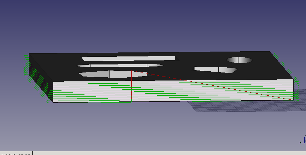
The clearance/safe height issue remains and this might help you whenever you get to it. In this image, the cutter would perform a rapid move all the way from clearance to the first section height. That would be a crash because it’s cutting through material from safe-height to start-depth. It correctly performs a feed move between section layers but not to the first section. Setting the start depth to the top of the material doesn’t work because then the first entire profile is done without cutting anything.
Working more with Projection and sections I hit some weirdness.
I want to create a solid that represents the outside perimeter without the inside holes. Then I can subtract the original part from it to find the material to be removed without worrying about the perimeter profile. I call this part the ‘envelope’ and I wrote a macro to create it.
import Path
from PathScripts import PathUtils as PU

obj = Gui.Selection.getSelectionEx()[0].Object

def getEnvelope(shape):
    area = Path.Area(Fill=1, Coplanar=0).add(shape)
    area.setPlane(Part.makeCircle(10))
    sec = area.makeSections(heights=[1.0], project=True)[0].getShape(rebuild=True)
    return sec.extrude(FreeCAD.Vector(0, 0, shape.BoundBox.ZMax))

Part.show(getEnvelope(obj.Shape))
But when I repeatedly run the macro with the same original part, I get different results for the envelope. Image below shows the original part at left, and envelopes created from four runs. The first and third are correct but the other two are wrong in different ways. I assume Area is caching the added shapes but I’m not sure how to clear it. drilling.fcstd (232 KB)
This probably has something to do with the loop orientation bug you’ve found early, and the problem is a complex one. I’ll propose a compromised change, and I want your opinion first. The change is to limit the orientation as 0=None, and 1=Reversed. The reason is that the CW and CCW notion actually depends on whether the wire is for outline or inner hole. Profiling operation contain both type of wires, while pocket (if the pattern are closed wires) are all inner wires. For inner wires, the material is in fact at the opposite side comparing to the outer wire. So for climb milling you’ll want CW for outer wire, and CCW for inner wire.
OCC, when making face, use CCW for outer wire and CW for inner wire. However, the problem is complicated by the fact that CW and CCW depends on the direction of the surface normal, or in layman’s term, depends on which direction you are looking at. To make things manageable, Area will make an assumption that the face normal shall be pointing towards (0,0,1) direction. WorkPlane is used to let user control how to transform the actual wire plane into this direction. In another word, Area will internally transform the wire so that the work plane’s normal align with (0,0,1) before any further processing. Before orientation adjustment, Area shall normalize all wires orientation, so that the outer wire is CCW, and inner wires is CW with regarding (0,0,1) direction. So now, you can see why it makes sense to just having two options for orientation. ‘None’ means keep the original orientation, which corresponds to conventional milling, and ‘Reversed’ for climb milling.
Path.fromShapes() will not have enough information to determine which wire is supposed to be outer and which is inner. So it just assumes the orientation of the input wires are already normalized, and simply reverse it if orientation=‘Reversed’. Any suggestion?