Does the FreeCAD FEM workbench has support for a parametric/optimizing solver?
What I specifically mean, in case my terminology is off, is the type of solver where for example I could link a plate’s thickness to the FEM solver and solve until some check condition is met (e.g. max von Mises < 100MPa), increasing the plate thickness each FEM iteration (so the following would automatically take place: change thickness → remesh → solve → check results object for condition → if condition not met then loop).
I know that the procedure above is doable using Python macros, but I’m considering writing a GUI for it and would like to verify that no one has already done it .
Thank you for the info! Good to verify that such a tool doesn’t exist, wouldn’t make sense to duplicate work.
Beso, while really cool and useful, is not really the same thing. Beso can only optimize the inner portion of a mesh, but the concept i am talking about allows for optimization/brute-forcing needed mesh (external) dimensions.
I cooked up a proof-of-concept GUI tool for the idea. It’s a bit janky at the moment, but enough for a proof-of-concept and to see if there’s any feedback after i publish it in the coming days.
The “changes” table contains all the values that will be changed each iteration, so when i enter “-250mm”, then every iteration the selected property (“Box.Length”, in demo vid) will have 250mm subtracted from it. The values will be reset to the original values after iterations have finished. The value type of “unit string” means that it gets parsed by Units.Quantity.
The “checks” table contains checks that need to pass. The checks are Python expressions that are evaluated and checked if they’re truthy or not. They get a couple of variables defined for them — iteration count (variable i) and latest FEM result object (variable r). If all checks return a truthy value then the iterations are stopped and the last result is the one that passed.
The part of the video where i add the check shows me selecting some random property. It doesn’t use the selected object and prop in any way and just evaluates the expression. I’ll rework that to just accept an expression without any linked objects, as i don’t think there’s too many use cases where people might want to check anything besides the FEM result. The object selection was a bit of spur-of-the-moment non-logic .
Only supports CalculiX and Gmsh at the moment, could not figure out how to interface with Netgen from Python.
I’ll clean up the code a bit and make it public in the next couple of days.
NB: i wanted to post a nice 900kb H264 encoded video, but the forum software didn’t let me, so this dithered gif will have to do
Do you think a good tutorial level example could be, for example, the optimisation of the proportions of an IPN profile?
All I can do myself is encourage you and test/crashrun things if you’d like. I operate windows portable versions, and not ready to step-up to github, so to test code I need the files and where to place them in the FreeCAD path (or instructions on where to copy paste some bits).
It uses gmsh which, as far as I know, is currently the preferred mesher for many things in FreeCAD.
It uses CCX, which is the main solver for FEM, so you’re doing it right.
If you ever want to adapt it to Elmer, I’m happy to try to help in any way.
Do you think a good tutorial level example could be, for example, the optimisation of the proportions of an IPN profile?
Maybe so. The reason why i wrote the previous (very hardcoded and non-GUI) version of this macro was to calculate optimal material thickness.
I added a quick example of what i did into the attachments. It’s a simple part that would attach to something with the middle hole and then have some weight attached to the outer holes. The part would be welded together from some sheet metal. Using this tool i can brute force the optimal material thickness.
Though this example could be improved by calculating it as a 2D mesh with the thickness modifier, but i’m not that familiar with that side of the FEM workbench .
All I can do myself is encourage you and test/crashrun things if you’d like. I operate windows portable versions, and not ready to step-up to github, so to test code I need the files and where to place them in the FreeCAD path (or instructions on where to copy paste some bits).
No problem, installation is pretty easy. Just drop the files into your FreeCAD user macros folder (See Macro->Macros->User macros location from FC menubar if you don’t know your location) and then run the FEMIterateGui macro from FreeCAD. It’s all in Python so it should work fine with any recent FreeCAD version.
You can get the files from github (green “Code” button and then “Download zip”).
When trying it out then make sure to save all other documents in FreeCAD, as this runs single-threaded and can freeze up the GUI when something goes wrong. View it as a proof-of-concept .
It doesn’t save any files onto disk so once you close the dialog then everything you entered will be lost! Most things not implemented are grayed out to avoid confusion, the grayed out mesh and analysis object selectors are working but used with the Select button.
Feedback is welcome!
I published the code here: https://github.com/svenvvv/fc-femiterate, there are still some issues that i mention in the README file.
Modifying spreadsheet rows is possible (as exhibited in the demo), but the properties are shown by cell coordinates, not label (so B4, not wall_thickness).
Gmsh at times displays a message of “Error in dimension”, but i’m not sure on how to interpret that.
This time the attached video is a even worse, it’s impossible to make nice gifs that don’t bloat in size. I’ve mirrored the two videos i’ve posted on my server in a bit nicer quality. They won’t be there forever since there’s not that much disk space, but by then this post will be outdated anyways . http://5.101.119.166/vids/femiterate-demo-1.mp4 http://5.101.119.166/vids/femiterate-demo-2.mp4 femiterate-demo-obj.FCStd (74.3 KB)
Updated version is a bit more usable.
Added saving of the settings (iter limit, checks and changes, custom expressions) into the FreeCAD document file, plus some bugfixes.
I’ve added the same wall thickness demo as an attachment, but this time it should be possible to open it up, launch the macro and have all the checks and changes that i prepared loaded in, so just have to click “Begin”. The solving should complete in 3 iterations and takes 13.6 s on my computer (fairly modern desktop). Should be a bit less painful to try out, so who’s interested should give it a try .
Settings are saved on clicking “Begin” or closing the dialog with the “Ok” button.
The meshing has some issues at bigger cell sizes, if someone has any ideas on what i should do differently to fix it (in the FC model itself) then i’d be thankful to hear them. Also once it took 5 iterations for some reason, seems like there are still some other quirks.
Hi, very interesting work.
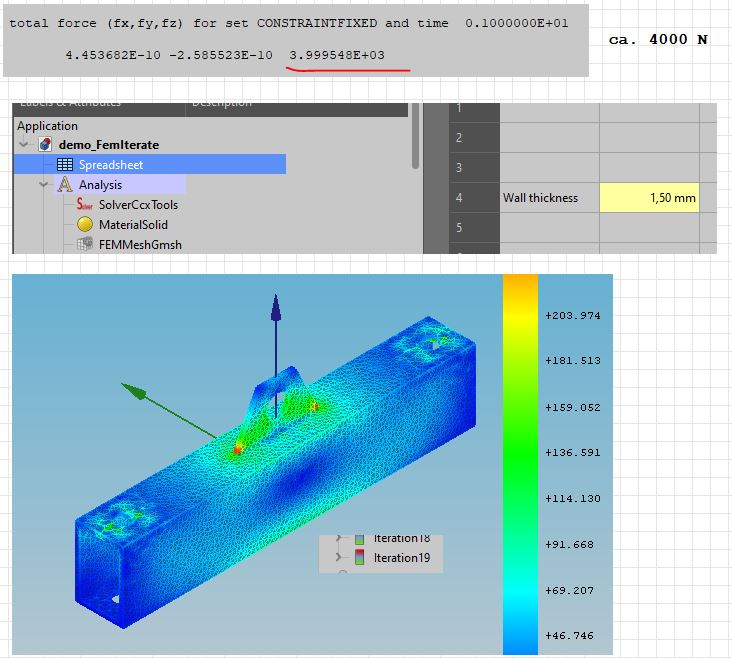
I ran your example with the predefined values, macro runs.
My workflow:
open file, remesh part (max el-size 2 mm), write inp, close dialog, run macro.
When I understand your macro right, it does this:
Start with 1,5 mm wall thickness as described in spreadsheet,
change thickness with 0,25 mm every step until max-sigma 150 MPa in the wall alone is reached. Right?
If so, this is exactly what in need for calculating flange-stiffeners
I run on intel i5 16 GB-Ram HP-laptop.
FreeCAD:
OS: Windows 10 (10.0)
Word size of OS: 64-bit
Word size of FreeCAD: 64-bit
Version: 0.19.24267 (Git)
Build type: Release
Branch: master
Hash: b2ca86d8d72b636011a73394bf9bcdedb3b109b7
Python version: 3.6.8
Qt version: 5.12.1
Coin version: 4.0.0a
OCC version: 7.3.0
Locale: German/Germany (de_DE)
@svvv:
some hints:
try to avoid mixing part-design and part for running fem.
Netgen does not work. I guess the reason is, that netgen reacts parametric by itself
when changing the geometry. Mesh the part with netgen and change the height of the plate, netgen
does remeshing instantly.
The terminology isn’t very good yet either, i think i’ll rename “checks” to “conditions”. “Chances” also sounds a bit off, but i can’t think of a better fitting word. Feel free to suggest better names for other wonky sounding labels as well .
I stuck this up top as i’ll be using that terminology from now on in this post.
First, a huge thanks for testing it out and taking screenshots!
The necessary workflow is: open file, run macro. It should take care of all the rest.
The file has to contain: FEM analysis object, FEM mesh and a FEM solver. FEMIterate should find them all automatically, but if it doesn’t then it’s possible to select them manually from the “Objects” tab.
It won’t hurt to mesh and solve once by hand just to see that all is working well, as it should delete all previous FEM results. This does mean that it is not possible to edit the solver input file, FEMIterate will simply overwrite all the edits.
No, it doesn’t discriminate any part of the result mesh. The condition will have to apply for the whole result mesh.
Other than that, it’s exactly the function of this tool.
On the picture you posted there is a message in the Log box: “Hit iteration limit without finding a solution”. That means that it ran for 20 times but the conditions didn’t pass. I’ll color the errors red so they’re a bit more noticeable at a quick glance.
I am not sure why that happened. If you check the FEM mesh results is the wall thickness increasing with each iteration?
It would be cool to allow to have different conditions for different groups of the FEM result, but i have no idea on how to implement it. The way it works is that the r variable in the condition expression gets set to the FEM result object for that iteration (labeled IterationX). So the “max(r.vonMises)” takes the maximum result from the values array. It just contains an array of numbers and i don’t know if/how it’s possible to associate them with volumes for conditions.
To test out more complex conditions one could do a calculation with the built-in solver, send the FEM result to the Python console via the right click menu and then assign it to r (“r = obj” in Python console). After that expressions can be entered exactly the same way as in the FEMIterate tool (sans other variables, but you get the gist). Expressions should return a truthy value (True or not 0) for FEMIterate to mark that condition as passed. All conditions must pass for the iteration to stop.
Thanks for the tip! I’m not that used to the Part Design boolean tools yet. Is there some documentation i could read on why i shouldn’t mix them?
Huh, if that’s the case then adding Netgen support will be simple. I’ll have to check that out. Thanks!
My FreeCAD info, just for reference:
OS: ArchLabs Linux (openbox)
Word size of OS: 64-bit
Word size of FreeCAD: 64-bit
Version: 2021.311.24301 +3373 (Git) AppImage
Build type: Release
Branch: LinkStage3
Hash: 91ca94db328bf6126c4a01547b6aa2202d876ebc
Python version: 3.8.8
Qt version: 5.12.9
Coin version: 4.0.1
OCC version: 7.4.0
Locale: English/United States (en_US)

Using the bundled CalculiX and gmsh
ccx ver 2.17.
gmsh ver 4.7.1-git-7d4ca23
No, I still get the full iteration-limit. Even when playing with the parameters.
There is a little difference in the stresses between 1. and 20. iteration, but no
visible change in the result-meshes.
There is no “official” advice to avoid mixing part-design/part wb for FEM.
But my experience is that meshing works better when using part-wb alone.
Here is a “real-life” part from my work. In 90% of my work I use netgen. Runs faster and mostly
the first meshing-run is ok. Especially when you have fillets. With gmsh you must
use mesh-refinement for the bore-holes/fillets. flange_stiffeners.FCStd (128 KB)
So far so good. Thanks for your work and have a nice remaining sunday.
That’s maybe true in FC master branch. I assume the most important is to check that the object has no error with Part_CheckGeometry
My FreeCAD info, just for reference:
OS: ArchLabs Linux (openbox)
Word size of OS: 64-bit
Word size of FreeCAD: 64-bit
Version: 2021.311.24301 +3373 (Git) AppImage
Build type: Release
Branch: LinkStage3
>

BTW the Linkstage3 branch ease to mix PartDesign and Part workflow. That not means the geometry that you've got has a better quality, Part_CheckGeometry again.