YEAH works great here too. Understood your code now. I had never used multiple inheritance before. It does write the Heading, Materials, Nodes, Elements and Loads for me.
I had been take this code from compas-fea repo!, although it is not hard to write it.
BTW: I don’t understand how can i give your code and apply it in my code. although i can add it by hand, but i want to learn how? I asked it in this related topic.
on master Branch They give the following accepted errors ATM
$
$ codespell -q 2 -S *.ts  -L childs,dof,dum,methode,nd,normaly,uint,vertexes,freez  src/Mod/Fem/
src/Mod/Fem/femsolver/z88/writer.py:354: Programm  ==> Program
$ find src/Mod/Fem/ -name "*\.py" | grep -v InitGui.py | grep -v tokrules.py | grep -v TestFem.py | xargs -I [] flake8 --ignore=E266,E722,W503 --max-line-length=100 []
src/Mod/Fem/femtest/app/test_ccxtools.py:180:9: F841 local variable 'test_name' is assigned to but never used
src/Mod/Fem/femtest/app/test_ccxtools.py:181:9: F841 local variable 'base_name' is assigned to but never used
src/Mod/Fem/femtest/app/test_ccxtools.py:182:9: F841 local variable 'analysis_dir' is assigned to but never used
$
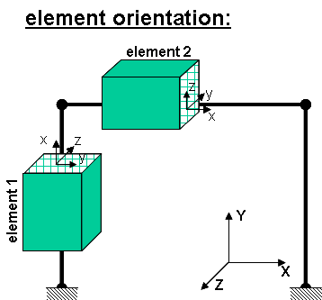
In continues this post, also for defining transformation in OpenSees i need to know which element has which direction to assign proper section properties to it. thanks.
@bernd. I analysed this model successfully with opensees. but still i can’t assign proper section to each element, can you please tell me? arzoomandi.FCStd (116 KB)
thanks, you mean i must assign Elementrotation1D to each beam or column or a bunch of those?
@bernd, i think if we create another workbench that specially suite for structural engineering is useful, because FEM workbench is very general workbench. like csiamerican products sap2000 and etabs. sap2000 is a general FEM program, while etabs is suite specifically for structural engineering. in real word we only need beam-column and shell element and later for nonlinear analysis some additional element that thos also has 1D or 2D dimensions. what is your opinion?
I am totally with you. Something between Arch (BIM) and FEM. Something which uses the Arch structural nodes and makes in put of loads an load combinations very easy. There is just one little problem with this. TIME … I have this in mind for years, but never started to do some serious code in this regard.
@bernd, I can view the displacement of model in 3 DOF system, but when i create a 3D model with 6 DOF, paraview don’t show displacement of structure. this is my opensees FreeCAD model, in this post. i send you a PR. to run this you must merge that.
also i want to apply result class in opensees. opensees gives me *.pvd output.