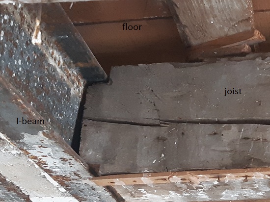
Let’s say we have an oak joist (15 cm x 15 cm x 370 cm), which is “fitted” in the profile of an I-profile beam (height 140 mm, width 66 mm), and the surface where the joist is laid is too small.
Among many possible solutions, I would like to study the right dimensions for the following blue metallic part:
Hypothesis:
the joist has to support 500 kg
we neglect the question of the resistance of the I-profile beam here
the blue metallic part is taken from a steel angle iron, but cut to have the desired shape:
Question: is a 100 x 100 mm (thickness 10 mm), and 20 cm length, steel angle iron enough?
You can ask your timber supplier, they may have a joist hangers.
You can also check if there is a code from your country. It may has a equation to size the screw.
If you want to do it with fem, try to find a screw example.
Like this.
The part wants to rotate, you get high shear forces in the bolts.
See dat-file, z-forces, after running sim.
File with cleared mesh:
joist.FCStd
pic_joist.JPG
When I open the FCStd file, how to display the metallic blue part (it seems hidden by default ?) and the FEM simulation ?
Is there a steel angle iron thickness which would be acceptable : probably 10 mm is ok? Would 8 mm or 6 mm be ok as well ?
Thanks once again !
PS:
I cannot put any bolt on the top of the joist, because there’s the upper floor above the joist. Was your simulation made with bolts on the top @thschrader ?
It’s based on a L-shaped angle iron, so it’s only on one side of the joist, not both sides.
Click on “BooleanFragments” in model-tree, press spacebar for activating/deactivating the part.
The FEM-run itself is based on the Compound (see part-wb), NOT on the BooleanFragments.
Re-run FEM:
Doubleclick on “Analysis” in model-tree, FEM-wb starts.
Doubleclick on mesh, remesh part.
Activate solver, run FEM.
Enjoy results…
There are tons of designs possible for your connection.
I simply did a fast approach based on you picture.
I didn’t find this “Mesh / Remesh part” option, is it in a menu or a toolbar icon? (which one?)
I also didn’t find “Activate solver”, would you have a screenshot?
Oh this is interesting! I’m interested for a simple solution: the difficulty is that the floor is already there above, so it’s not easy to insert a part (for example it’s impossible to insert a U-shape part).
What kind of shape would you use thschrader?
Here you can see there is already a wooden floor above (Nota: the joists look old, but they are still very strong and hard oak):
See pics.
Open the joist-file.
Doubleclick on “Analysis” in model-tree, FEM-wb starts.
Doubleclick on “FEMMeshGmsh” in modeltree, mesher dialog opens, press apply.
After meshing is done:
Click on “SolverCcxTools”, the solver icon switches from grey to yellow.
Click on that icon, the solver dialog opens, write the inp-file, run analysis.
In your photo it looks like that the steel beam isnt a 140x66 mm I-Profile,
but 2x U-profile with something in between. Is that right? Dimensions?
Looks like that the I-beam is tilted against the wooden beam.
I would do this:
2x vertical stripes with slotholes, L80-profile below the wooden beam,
slotholes are for adjusting height, 2x M12 10.9 bolt, 50 kN prestressing.
joist2.FCStd
proposal1.JPG
EDIT:
The new steel-clamp doesnt carry any dead-load of the existing floor, only additional loading.
A backdraw is, that the upper fixing of the clamp can tilt the I-beam even more. Mmmh…
Thanks a lot thschrader for the screenshots about FEM, for this new idea, and for the time spent!
In your photo it looks like that the steel beam isnt a 140x66 mm I-Profile,
but 2x U-profile with something in between. Is that right? Dimensions?
There are two 140x66 mm I-Profile (I can confirm this), and (I think) concrete in the middle.
One of the two is tilted indeed, but I think it is like this since ~80 or 100 years, I think it has been installed like this.
I would do this:
2x vertical stripes with slotholes, L80-profile below the wooden beam,
slotholes are for adjusting height, 2x M12 10.9 bolt, 50 kN prestressing.
Nice solution! I understand the part below the wooden-beam is a classical L-shaped profile, but what about the top part? Can this part be easily found, or do need someone to solder it? Or is it a “bended” vertical stripe?
PS: I am curious if there is a solution that does not take some height below the wooden beam (to avoid having to put the ceiling lower).
Thanks thschrader! I’ll probably do this!
Do you think it’s possible with off-the-shelf parts (found by my local shop) and bolts, or does this require soldering ?
\
Also last question about FEM: I managed to run the meshing + the SolverCcxTools “Write .inp” then “Run CalculiX”. But then I don’t see the nice picture that you posted (https://forum.freecad.org/download/file.php?id=228881), instead I have this:
Where should I click to display the results in a nice way like you did?
I am late coming to this post but I am wondering if this arrangement would work?
It would depend upon how much clearance you have between the top of the steel members and the flooring. you would need about 30mm perhaps.
I have suggested two 10mm (12mm would be better) thick plates holed to take 4 x 16mm threaded rods with 16mm nuts and flat washers. You would have to get the plates made but I wouldn’t think they would cost much. The threaded rods, nuts and washers can be bought from a major hardware store.
If you haven’t got much clearance you might have to get the holes on the top plate threaded for the 16mm threaded rods.
Hopefully as the bottom nuts are gradually tightened up this would align the lower and upper surfaces of the “C” channels and timber joists - that would be a desirable outcome.
It might be worthwhile hiring a builders (Acrow) adjustable prop to help you get the twist out of the steel beam - after you have set the plates up!! (don’t want the floor to collapse on you!!)
From a pure mechanical point of view, your solution is the best,
because you grab all parts. And force them to stay connected via prestressing the bolts.
Thats how I understand your idea.
Yes that is what I intended Thomas. It is a complex situation though isn’t it? - a job for a professional as you advised
Nevertheless I thought I would have a try at analysing the plate
The questions that come to my mind are:-
How much load has to be applied to the bolts to align the beam and joist? Then>>>
How much additional load is placed on the connection by the floor loads? Then>>>
What factor of safety should be applied?
BTW
Is it possible, to define Pre-Tension for bolts etc. in FC FEM?
As far as I remember, a general way is, to lower the temperature of the specific elements, to use temperature effect.
Maybe, there is a direct/better way in FC-FEM?