I am running windows 10 freecad .17 13522 git
I assembled some parts the dragonplate carbon fiber pieces I modeled using assembly2.
Now I get a error when I gmesh it.
The other generator works but the solver does not it says 0.0: Check dependencies…
I am using tubes maby that shape is not good for this? ![]()
![]()
![]()


0.0: We are going to start …
0.0: Start Gmsh …
3.7: Gmsh had warnings …
3.7: Warning : OCC Project Point on Surface FAIL Warning : OCC Project Point on Surface FAIL Warning : OCC Project Point on Surface FAIL Warning : OCC Project Point on Surface FAIL Warning : OCC Project Point on Surface FAIL Warning : OCC Project Point on Surface FAIL Warning : OCC Project Point on Surface FAIL Warning : OCC Project Point on Surface FAIL Warning : OCC Project Point on Surface FAIL Warning : OCC Project Point on Surface FAIL Warning : OCC Project Point on Surface FAIL Warning : OCC Project Point on Surface FAIL Warning : OCC Project Point on Surface FAIL Warning : OCC Project Point on Surface FAIL Warning : OCC Project Point on Surface FAIL Warning : OCC Project Point on Surface FAIL Warning : OCC Project Point on Surface FAIL Warning : OCC Project Point on Surface FAIL Warning : OCC Project Point on Surface FAIL Warning : OCC Project Point on Surface FAIL Warning : OCC Project Point on Surface FAIL Warning : OCC Project Point on Surface FAIL Warning : OCC Project Point on Surface FAIL Warning : OCC Project Point on Surface FAIL Warning : OCC Project Point on Surface FAIL Warning : OCC Project Point on Surface FAIL Warning : OCC Project Point on Surface FAIL Warning : OCC Project Point on Surface FAIL Warning : OCC Project Point on Surface FAIL Warning : OCC Project Point on Surface FAIL Warning : OCC Project Point on Surface FAIL Warning : OCC Project Point on Surface FAIL Warning : OCC Project Point on Surface FAIL Warning : OCC Project Point on Surface FAIL Warning : OCC Project Point on Surface FAIL Warning : OCC Project Point on Surface FAIL Warning : OCC Project Point on Surface FAIL Warning : OCC Project Point on Surface FAIL Warning : OCC Project Point on Surface FAIL Warning : OCC Project Point on Surface FAIL Warning : OCC Project Point on Surface FAIL Warning : OCC Project Point on Surface FAIL Warning : OCC Project Point on Surface FAIL Warning : OCC Project Point on Surface FAIL Warning : OCC Project Point on Surface FAIL Warning : OCC Project Point on Surface FAIL Warning : OCC Project Point on Surface FAIL Warning : OCC Project Point on Surface FAIL Warning : Surface mesh: worst distortion = -6.45584 (avg = 0.496641, 418 elements with jac.
3.7: Gmsh done!
Try to use 2D-shell elements.
The “pipe” you see has a diameter of 10 mm and a length of 1000 mm.
In FEM, you can define a shell thickness. No need to use 3D-meshing.

I got errors again. I did not go that far I made a cube chamfered and the other one like that some edges. Gmeshed it and got errors. A normal cube no error Because I was surprised then and wondered if I had something installed wrong but it is just win 10 and the latest stable freecad release. ???
Can you post your FC-file with your model?
To reduce file-size: in model-tree, right click on FEM-mesh, then “clear mesh”
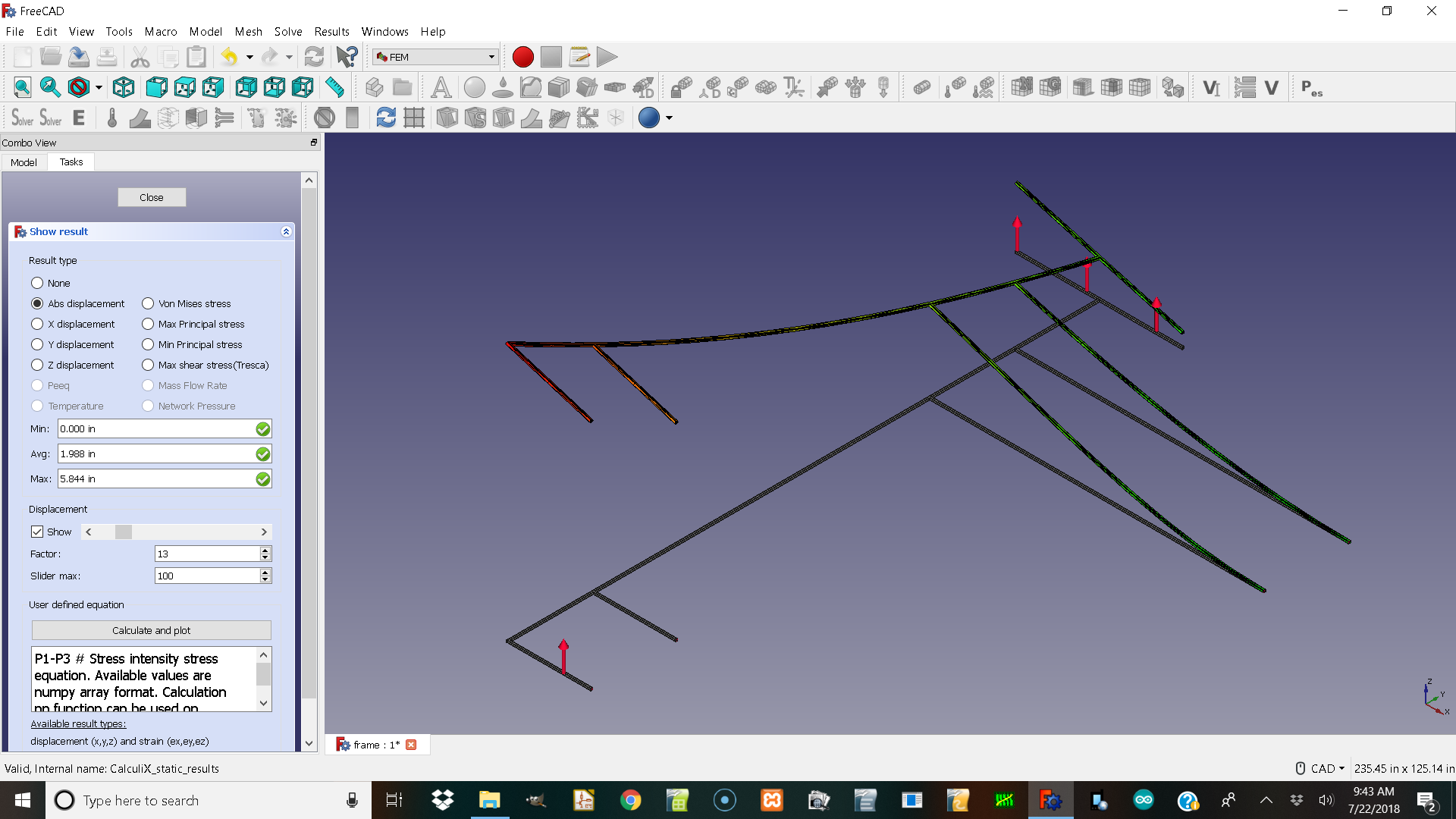
I got a solver to work! ![]() I tried re-running the examples they ran. I tried asking myself what is different.
I tried re-running the examples they ran. I tried asking myself what is different.
Material I was selecting aluminum… in examples I seen calculix steel and wood for the fem popsicle stick bridge example.
If you select aluminum it stops at check references…
I made a simple half frame out of a block sketch extruded .5"
The shell tool in parts workbench did not seem to work.
The fem shell tool looks like it is for faces but realy I would want a hollow of my 3d model?
Well I am glad to see the simulation run now I wonder if I can make the dragon plate carbon fiber tube material.
![]()
![]()
![]()
here is all of them but one.
skeleton frame.FCStd (208 KB)
pcft_5_4_98_in.FCStd (10.8 KB)
pcft_5_4_72_in.FCStd (10.8 KB)
pcft_5_4_48_in.FCStd (10.8 KB)
pcft__5_4_24_in.FCStd (10.8 KB)
oh 2 here are all of them.
threaded_tube_connector.FCStd (14.8 KB)
cube_v_threaded_1_in.FCStd (38.3 KB)
gmesh does not seem to close and it throws a error when trying to run the solver volume in geometry like error.
Hi josheeg,
I had a look at your files.
The easiest way is to calculate the tubes “by hand” and use FEM only
for the connection-cubes.
Rerun FEM:
Load my FC-file.
In model-tree: doubleclick an analysis activates FEM-wb
doubleclick on mesh (model-tree) open mesh-dialog, remesh.
run solver.
For me alu works.
cube_v_threaded_FEM.FCStd (42.8 KB)

Why would I not assemble them can I just model them all as carbon and watch what changes color and deforms I don’t know how to hand calculate the tubes.
Here is what I have as aluminum in the picture it is a windows 10 newest freecad no other programs.

The connector for the tubes that has the exact OD as the tubes ID so I wonder if the material choice and the assembly didnt properly manafold like I expected. In other words maby if I want to assemble something make the bolts bigger than the holes so the boolian merge in assembly2 or part workbench can make them manafold to do fem on them?

WOuld you post your FreeCAD info, it seams you run 0.17 stable … The aluminium got an fix in 0.18 … 0c6ed4
I will soon thanks it’s great to know those are working. And thanks for showing how it was fixed in git I like how it version controls.
Can things be assembled and fem Ed?
Is it a mux in fem I should use and should things be bigger than the hole so the meshes overlap to make it boolian join and weld the manafold step file for fem?
depends … if you would like to use two different materials, no they should not overlap, they should share a face, the connection face. A CompSolid is your friend. Use Part Boolean Fragment to create them. See FEM_Shear_of_a_Composite_Block
I tried 0.18 that is not a official release and I still got a error in the bottom left corner when I selected it in windows 10. it was aluminum number …
So if I want to do a fem analysis on a carbon fiber tube system from dragon plate. I would get the tube properties and assume the aluminum connectors are similar in strength. Then I should boolian join them by making the parts that connect make one side larger. ?
The overlap could even represent the chemical welds.
![]()