FE Meshing a Fabrication Direct From CAD

O Learned Denizens, I humbly prostrate myself before your collective wisdom once more.

I have received yet another STEP file, this time of quite a simple fabrication.

I want to run some finite element analysis on it, but at present when I run GMSH it meshes most of the structure but misses two tubes out when the file is imported with STEP Compound Merge enabled. If I run Netgen then I get a beautiful mesh over the whole component…that is only a surface mesh with no tetrahedrals in it.

If I import the file without STEP Compound Merge then I can mesh each part individually using GMSH without difficulty, but the problematic items from the first go only have a surface mesh on them.

Anyone got any advice on what features of the CAD cause the mesher to fail like this? It’s basically a tube with an end cut made by another tube, the two that are failing; another tube in the fabrication meshes just fine.

After I have it all meshed, I will be back with more questions about “constraint tie”, I am sure.

Damian

Without the CAD file that’s not so easy to help.
I assume the issue is due to your model which is certainly a mix of shells and solids.
You have to Part_CheckGeometry your model first.
Then adjust it to get only 1 shell or only 1 solid to mesh.
FEM workbench doesn’t handle multi-mesh.

Moved to FEM forum.

So my next question is how to run the geometry check?

https://wiki.freecad.org/Part_CheckGeometry - got it.

“1 processed out of 1 selected
0 invalid shapes.”

The file is attached.

I can parse the source file to see what’s in it.

awk '/^#[0-9]/ { print $3 }' ArmSample.STEP | sort | uniq

I see all sorts of things:

ADVANCED_BREP_SHAPE_REPRESENTATION
ADVANCED_FACE
APPLICATION_CONTEXT
APPLICATION_PROTOCOL_DEFINITION
APPROVAL
APPROVAL_DATE_TIME
APPROVAL_PERSON_ORGANIZATION
APPROVAL_ROLE
APPROVAL_STATUS
AXIS2_PLACEMENT_3D
B_SPLINE_CURVE_WITH_KNOTS
B_SPLINE_SURFACE_WITH_KNOTS
BOUNDED_CURVE
CALENDAR_DATE
CARTESIAN_POINT
CC_DESIGN_APPROVAL
CC_DESIGN_DATE_AND_TIME_ASSIGNMENT
CC_DESIGN_PERSON_AND_ORGANIZATION_ASSIGNMENT
CC_DESIGN_SECURITY_CLASSIFICATION
CIRCLE
CLOSED_SHELL
CONICAL_SURFACE
CONVERSION_BASED_UNIT
COORDINATED_UNIVERSAL_TIME_OFFSET
CYLINDRICAL_SURFACE
DATE_AND_TIME
DATE_TIME_ROLE
DESIGN_CONTEXT
DIMENSIONAL_EXPONENTS
DIRECTION
EDGE_CURVE
EDGE_LOOP
FACE_BOUND
FACE_OUTER_BOUND
GEOMETRIC_REPRESENTATION_CONTEXT
LENGTH_MEASURE_WITH_UNIT
LENGTH_UNIT
LINE
LOCAL_TIME
MANIFOLD_SOLID_BREP
MECHANICAL_CONTEXT
NAMED_UNIT
ORGANIZATION
ORIENTED_EDGE
PERSON
PERSON_AND_ORGANIZATION
PERSON_AND_ORGANIZATION_ROLE
PLANE
PRODUCT
PRODUCT_DEFINITION
PRODUCT_DEFINITION_FORMATION_WITH_SPECIFIED_SOURCE
PRODUCT_DEFINITION_SHAPE
PRODUCT_RELATED_PRODUCT_CATEGORY
SECURITY_CLASSIFICATION
SECURITY_CLASSIFICATION_LEVEL
SHAPE_DEFINITION_REPRESENTATION
UNCERTAINTY_MEASURE_WITH_UNIT
VECTOR
VERTEX_POINT

So a simple admonishment about mixing shells and surfaces doesn’t seem to cut it.

If I pick one of the problem items I can ask to convert it to a solid, in case it isn’t already. I get this message:

15:04:50  ArmSample is ignored because it is already a solid.

So then I ask GMSH to mesh it “from shape” with min element size 1.0 and max element size 4.0:

15:05:26  Fem::FemMeshObjectPython: Link(s) to object(s) 'Part__Feature' go out of the allowed scope 'FEMMeshGmsh009'. Instead, the linked object(s) reside within 'ArmSample'.
15:05:37    ElementDimension: 3
15:05:37    No Group meshing for analysis.
15:05:37    C:\Users\damia\AppData\Local\Temp\fcfem_ui9ap36g\Part__Feature_Geometry.brep
15:05:37    C:\Users\damia\AppData\Local\Temp\fcfem_ui9ap36g\Part__Feature_Mesh.unv
15:05:37    C:\Users\damia\AppData\Local\Temp\fcfem_ui9ap36g\shape2mesh.geo
15:05:37    C:/CL34-win64/bin/gmsh-2.7.0-Windows/gmsh.exe
15:05:37    New mesh was added to the mesh object.
15:05:37  Gmsh had warnings ...
15:05:37  Error   : Unknown number option 'General.NativeFileChooser'
Error   : Unknown number option 'Mesh.MeshSizeMin'
Error   : Unknown number option 'Mesh.MeshSizeMax'
Error   : Unknown number option 'General.NumThreads'
Error   : Unknown number option 'Mesh.MeshSizeFromCurvature'
Error   : Self intersecting surface mesh, computing intersections (this could take a while)
Error   : Could not open file 'intersect.pos'
Error   : ------------------------------
Error   : Mesh generation error summary
Error   :     0 warnings
Error   :     2 errors
Error   : Check the full log for details
Error   : ------------------------------

My previous messing around has taught me about the .geo file, so I retrieved it from the AppData folder to somewhere a bit more traceable and ran GMSH from the command line. It gives me a picture of a shell mesh and the following output:

Info    : -------------------------------------------------------
Info    : Reading 'shape2mesh.geo'...
Error   : Unknown number option 'General.NumThreads'
Info    : Reading 'C:\Users\damia\AppData\Local\Temp\fcfem_ui9ap36g\Part__Feature_Geometry.brep'...
Info    : Done reading 'C:\Users\damia\AppData\Local\Temp\fcfem_ui9ap36g\Part__Feature_Geometry.brep'
Error   : Unknown number option 'Mesh.MeshSizeFromCurvature'
Info    : Finalized high order topology of periodic connections
Info    : Meshing 1D...
Info    : Meshing curve 1 (BSpline)
Info    : Meshing curve 2 (Line)
Info    : Meshing curve 3 (BSpline)
Info    : Meshing curve 4 (BSpline)
Info    : Meshing curve 5 (BSpline)
Info    : Meshing curve 6 (Line)
Info    : Meshing curve 7 (BSpline)
Info    : Meshing curve 8 (BSpline)
Info    : Meshing curve 9 (Line)
Info    : Meshing curve 10 (BSpline)
Info    : Meshing curve 11 (BSpline)
Info    : Meshing curve 12 (Line)
Info    : Meshing curve 13 (Line)
Info    : Meshing curve 14 (BSpline)
Info    : Meshing curve 15 (Line)
Info    : Meshing curve 16 (BSpline)
Info    : Meshing curve 17 (BSpline)
Info    : Meshing curve 18 (BSpline)
Info    : Meshing curve 19 (BSpline)
Info    : Meshing curve 20 (BSpline)
Info    : Meshing curve 21 (BSpline)
Info    : Meshing curve 22 (BSpline)
Info    : Done meshing 1D (0.328125 s)
Info    : Meshing 2D...
Info    : Meshing surface 1 (Cylinder, MeshAdapt)
Info    : Meshing surface 2 (Cylinder, MeshAdapt)
Info    : Meshing surface 3 (Cylinder, MeshAdapt)
Info    : Meshing surface 4 (Cylinder, MeshAdapt)
Info    : Meshing surface 5 (Cylinder, MeshAdapt)
Info    : Meshing surface 6 (Cylinder, MeshAdapt)
Info    : Meshing surface 7 (Cylinder, MeshAdapt)
Info    : Done meshing 2D (0.375 s)
Info    : Meshing 3D...
Info    : Delaunay Meshing 1 volumes with 1 connected components
Info    : Meshing volume 1 (Delaunay)
Error   : Self intersecting surface mesh, computing intersections (this could take a while)
Info    : 10 intersecting faces have been saved into 'intersect.pos'
Info    : Done meshing 3D (0.5625 s)
Info    : Meshing order 2 (curvilinear on)...
Info    : Meshing curve 1 order 2
Info    : Meshing curve 2 order 2
Info    : Meshing curve 3 order 2
Info    : Meshing curve 4 order 2
Info    : Meshing curve 5 order 2
Info    : Meshing curve 6 order 2
Info    : Meshing curve 7 order 2
Info    : Meshing curve 8 order 2
Info    : Meshing curve 9 order 2
Info    : Meshing curve 10 order 2
Info    : Meshing curve 11 order 2
Info    : Meshing curve 12 order 2
Info    : Meshing curve 13 order 2
Info    : Meshing curve 14 order 2
Info    : Meshing curve 15 order 2
Info    : Meshing curve 16 order 2
Info    : Meshing curve 17 order 2
Info    : Meshing curve 18 order 2
Info    : Meshing curve 19 order 2
Info    : Meshing curve 20 order 2
Info    : Meshing curve 21 order 2
Info    : Meshing curve 22 order 2
Info    : Meshing surface 1 order 2
Info    : Meshing surface 2 order 2
Info    : Meshing surface 3 order 2
Info    : Meshing surface 4 order 2
Info    : Meshing surface 5 order 2
Info    : Meshing surface 6 order 2
Info    : Meshing surface 7 order 2
Info    : Meshing volume 1 order 2
Info    : Finalized high order topology of periodic connections
Info    : Surface mesh: worst distortion = 0.745815 (0 elements in ]0, 0.2]); worst gamma = 0.0122395
Info    : Done meshing order 2 (0.078125 s)
Info    : 11368 vertices 6010 elements
Error   : ------------------------------
Error   : Mesh generation error summary
Error   :     0 warnings
Error   :     1 error
Error   : Check the full log for details
Error   : ------------------------------
Info    : Removing duplicate mesh vertices...
Info    : Found 0 duplicate vertices
Info    : No duplicate vertices found
Info    : Writing 'C:\Users\damia\AppData\Local\Temp\fcfem_ui9ap36g\Part__Feature_Mesh.unv'...
Info    : Done writing 'C:\Users\damia\AppData\Local\Temp\fcfem_ui9ap36g\Part__Feature_Mesh.unv'
Info    : Done reading 'shape2mesh.geo'

I note again the invitation to “check the full log for details”, but am none the wiser. So I thought I’d go to one of the tubes that does mesh and compare the output from GMSH:

Info    : -------------------------------------------------------
Info    : Reading 'shape2mesh.geo'...
Error   : Unknown number option 'General.NumThreads'
Info    : Reading 'C:\Users\damia\AppData\Local\Temp\fcfem_iabitafz\Part__Feature002_Geometry.brep'...
Info    : Done reading 'C:\Users\damia\AppData\Local\Temp\fcfem_iabitafz\Part__Feature002_Geometry.brep'
Error   : Unknown number option 'Mesh.MeshSizeFromCurvature'
Info    : Finalized high order topology of periodic connections
Info    : Meshing 1D...
Info    : Meshing curve 1 (Line)
Info    : Meshing curve 2 (BSpline)
Info    : Meshing curve 3 (Line)
Info    : Meshing curve 4 (BSpline)
Info    : Meshing curve 5 (BSpline)
Info    : Meshing curve 6 (Line)
Info    : Meshing curve 7 (BSpline)
Info    : Meshing curve 8 (Line)
Info    : Meshing curve 9 (BSpline)
Info    : Meshing curve 10 (BSpline)
Info    : Meshing curve 11 (BSpline)
Info    : Meshing curve 12 (BSpline)
Info    : Done meshing 1D (0.140625 s)
Info    : Meshing 2D...
Info    : Meshing surface 1 (Cylinder, MeshAdapt)
Info    : Meshing surface 2 (Cylinder, MeshAdapt)
Info    : Meshing surface 3 (Cylinder, MeshAdapt)
Info    : Meshing surface 4 (Cylinder, MeshAdapt)
Info    : Meshing surface 5 (Cylinder, MeshAdapt)
Info    : Meshing surface 6 (Plane, Delaunay)
Info    : Done meshing 2D (1.10938 s)
Info    : Meshing 3D...
Info    : Delaunay Meshing 1 volumes with 1 connected components
Info    : Meshing volume 1 (Delaunay)
Info    : 6175 points 31350 edges and 12350 faces in the initial mesh
Info    : Found region 1
Info    : 0 points created - Worst tet radius is 0.759992 (PTS removed 0 0)
Info    : 3D point insertion terminated (6175 points created):
Info    :  - 0 Delaunay cavities modified for star shapeness
Info    :  - 0 points could not be inserted
Info    :  - 19000 tetrahedra created in 0 sec. (-2147483648 tets/sec.)
Info    : Done meshing 3D (0.578125 s)
Info    : Optimizing 3D mesh...
Info    : Optimizing volume 1
Info    : Opti : STARTS with  1.12319E+05 QBAD  1.45038E-02 QAVG  7.13465E-01
Info    : Opti : 0.00 < QUAL < 0.10 :        74 elements
Info    : Opti : 0.10 < QUAL < 0.20 :       144 elements
Info    : Opti : 0.20 < QUAL < 0.30 :       170 elements
Info    : Opti : 0.30 < QUAL < 0.40 :       373 elements
Info    : Opti : 0.40 < QUAL < 0.50 :       624 elements
Info    : Opti : 0.50 < QUAL < 0.60 :      1255 elements
Info    : Opti : 0.60 < QUAL < 0.70 :      4291 elements
Info    : Opti : 0.70 < QUAL < 0.80 :      6755 elements
Info    : Opti : 0.80 < QUAL < 0.90 :      4911 elements
Info    : Opti : 0.90 < QUAL < 1.00 :       403 elements
Info    : Opti : (386,0,0) =  1.12319E+05 QBAD  1.23838E-01 QAVG  7.25504E-01 (   0.000 sec)
Info    : Opti : (395,0,0) =  1.12319E+05 QBAD  2.01075E-01 QAVG  7.25696E-01 (   0.000 sec)
Info    : Opti : no ill-shaped tets in the mesh ;-)
Info    : Opti : 0.00 < QUAL < 0.10 :         0 elements
Info    : Opti : 0.10 < QUAL < 0.20 :         0 elements
Info    : Opti : 0.20 < QUAL < 0.30 :         5 elements
Info    : Opti : 0.30 < QUAL < 0.40 :       378 elements
Info    : Opti : 0.40 < QUAL < 0.50 :       537 elements
Info    : Opti : 0.50 < QUAL < 0.60 :      1218 elements
Info    : Opti : 0.60 < QUAL < 0.70 :      4326 elements
Info    : Opti : 0.70 < QUAL < 0.80 :      6917 elements
Info    : Opti : 0.80 < QUAL < 0.90 :      4854 elements
Info    : Opti : 0.90 < QUAL < 1.00 :       402 elements
Info    : Done optimizing 3D mesh (0.015625 s)
Info    : Meshing order 2 (curvilinear on)...
Info    : Meshing curve 1 order 2
Info    : Meshing curve 2 order 2
Info    : Meshing curve 3 order 2
Info    : Meshing curve 4 order 2
Info    : Meshing curve 5 order 2
Info    : Meshing curve 6 order 2
Info    : Meshing curve 7 order 2
Info    : Meshing curve 8 order 2
Info    : Meshing curve 9 order 2
Info    : Meshing curve 10 order 2
Info    : Meshing curve 11 order 2
Info    : Meshing curve 12 order 2
Info    : Meshing surface 1 order 2
Info    : Meshing surface 2 order 2
Info    : Meshing surface 3 order 2
Info    : Meshing surface 4 order 2
Info    : Meshing surface 5 order 2
Info    : Meshing surface 6 order 2
Info    : Meshing volume 1 order 2
Info    : Finalized high order topology of periodic connections
Info    : Surface mesh: worst distortion = 0.818858 (0 elements in ]0, 0.2]); worst gamma = 0.468496
Info    : Volume Mesh: worst distortion = 0.598852 (0 elements in ]0, 0.2])
Info    : Done meshing order 2 (0.21875 s)
Info    : 37162 vertices 31499 elements
Info    : Removing duplicate mesh vertices...
Info    : Found 0 duplicate vertices
Info    : No duplicate vertices found
Info    : Writing 'C:\Users\damia\AppData\Local\Temp\fcfem_iabitafz\Part__Feature002_Mesh.unv'...
Info    : Done writing 'C:\Users\damia\AppData\Local\Temp\fcfem_iabitafz\Part__Feature002_Mesh.unv'
Info    : Done reading 'shape2mesh.geo'

So it seems the key line is:

Error   : Self intersecting surface mesh, computing intersections

Now, the real question is “what checks (other than the Part_CheckGeometry I’ve already run and found inconclusive) do I need to run to get ahead of this?”

OK, so when I get down to it, it becomes somewhat obvious:

Or here if the link is broken.

When two tubes of the same size are coped together, a sliver is the outcome, mathematically.

So that’s the sort of thing I need to be looking for.

Inconclusive? Come on… :unamused:
Part_CheckGeometry show 9 shells and 9 solids, and a lot of auto-intersections:
Part_Check_Geom_0WA - Custom LCA.png
Your model is not ready to mesh as is, far from it.
You have to clean your model first (remove small details, split eges, avoid tangencies with null thickness, remove small gaps, small holes, fuse solids, get a single shell, etc…) then mesh it.

OS: Debian GNU/Linux 10 (buster) (LXDE/LXDE-pi)
Word size of FreeCAD: 64-bit
Version: 0.20.31627 (Git)
Build type: Unknown
Branch: LinkDaily
Hash: 628ab90134e80886cb9bf8d6a6b6b07311514f10
Python version: 3.7.3
Qt version: 5.11.3
Coin version: 4.0.0a
OCC version: 7.3.0
Locale: French/France (fr_FR)

The results from your check are very different to the results that I got.

Can you be more explicit on how you are running the check? Because I am seeing this:

Or this if the link is broken.

If you look at the picture, I think my confusion is reasonable.

Of course the geometry isn’t ready to mesh! I am trying to get the mesher to guide me about what it objects to. But it seems there is more than one geometry check that can be run, so let’s start with that before getting too excited about everything else?

Btw. simplification is not just a matter of what can be meshed but there are also good practices recommended in most cases. The geometry should be clean, with no issues (even if it’s meshed somehow, there may still be some serious issues with it in such cases) and all unnecessary (especially small) details should be removed.

1- Yes, it’s maybe about your step import options
2- Yes, that’s why you should send your FreeCAD file instead of the step file, it avoids misleading.
3- As Newjoker said, don’t expect too much about the mesher. You have to clean your model yourself, you have to know good practices. We can help you BTW.

So, send your FC file, and send your FC infomations (see red ribbon “forum rules”).

Basically I know how to get a mesh from your model. But it needs some efforts, because the model is quite “dirty” as FEM is concerned.

OS: Windows 10 Version 2009
Word size of FreeCAD: 64-bit
Version: 0.20.29177 (Git)
Build type: Release
Branch: releases/FreeCAD-0-20
Hash: 68e337670e227889217652ddac593c93b5e8dc94
Python 3.8.10, Qt 5.15.2, Coin 4.0.1, Vtk 8.2.0, OCC 7.6.2
Locale: English/United States (en_US)

Attached are two versions of the file in FreeCAD. One has been imported with STEP Compound Merge enabled and one without it enabled.

None of that is telling me why your geometry check is different to my geometry check?

Maybe it’s due to OCC difference, or maybe that’s related to the linkdaily branch I’m using (I don’t think so BTW). I don’t know. Maybe bernd has a valuable opinion about such difference of diagnostic with Part_CheckGeometry.

I share here the file Lower_Arm2, 2D meshed. This mesh has not a so good quality because of the poor quality of the former model (in regards to FEM I mean). And I was too lazy to remove all split lines and to fine tun the 2D shell. Hence some regions are too much distorted with non positive jacobian elements as a result (the padeye junction on tube for eg.).
Anyway, the file shows you the way to do for 2D analysis. Many other workflows are possible.
Actually it would be easier to re-model the part from scratch, properly, with 2D FEM analysis in mind as a goal.

Below a gif to illustrate a FEM result (with CCX errors btw due to bad jacobian), fancy load case, just for fun:
Lower_Arm_2_FEM.gif
LowerArm_2_2Dmeshed_cleared.FCStd
30 sec to write inp file, then 20 sec to run CCX on my Raspberry PI4-4GB. 2D analysis is the key!

I have cleared the mesh, just run again the mesh object to re-create the mesh.
Now your turn to try :wink:

<Well, that got scrambled somehow. Edited to maintain my original intent.>

At the risk of sounding slightly obsessive, I am only really interested in the original question.

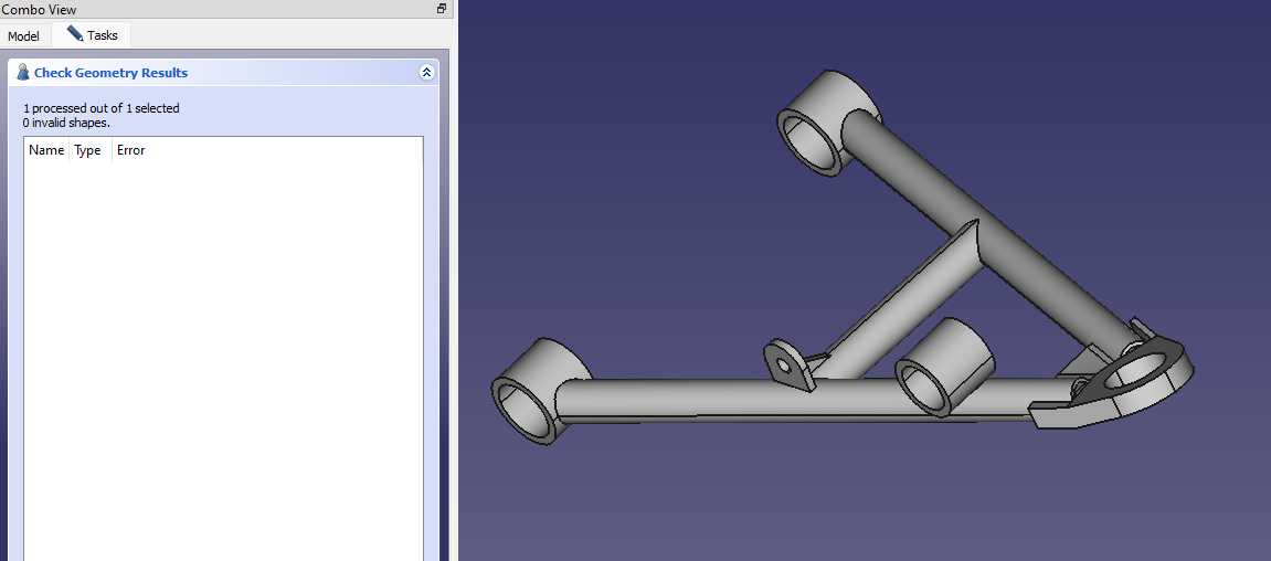
When I look at the other tube that won’t mesh, notwithstanding that my CheckGeometry is different to anybody else’s - and I’m no closer to understanding that, by the way - I am still pretty mystified about what the actual issue is.

I can go and find the .BREP file written out and passed to GMSH, and the specific shape2mesh.geo file for that tube. The “Report View” pane (bottom left on my screen) gives me the temporary folder name in AppData where the files are stored.

Running GMSH standalone produces the same error messages as in report view, including the rather cryptic “check full log for details”. No other log is actually evident to me. At the command prompt, GMSH reports 6 pairs of intersecting “facets”, all of which appear to be facet #8 and facet #3 at triangles 904, 12, 6844 and 9903, 9884, 904. To my untrained eye it looks like the same thing detected six times.

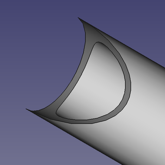
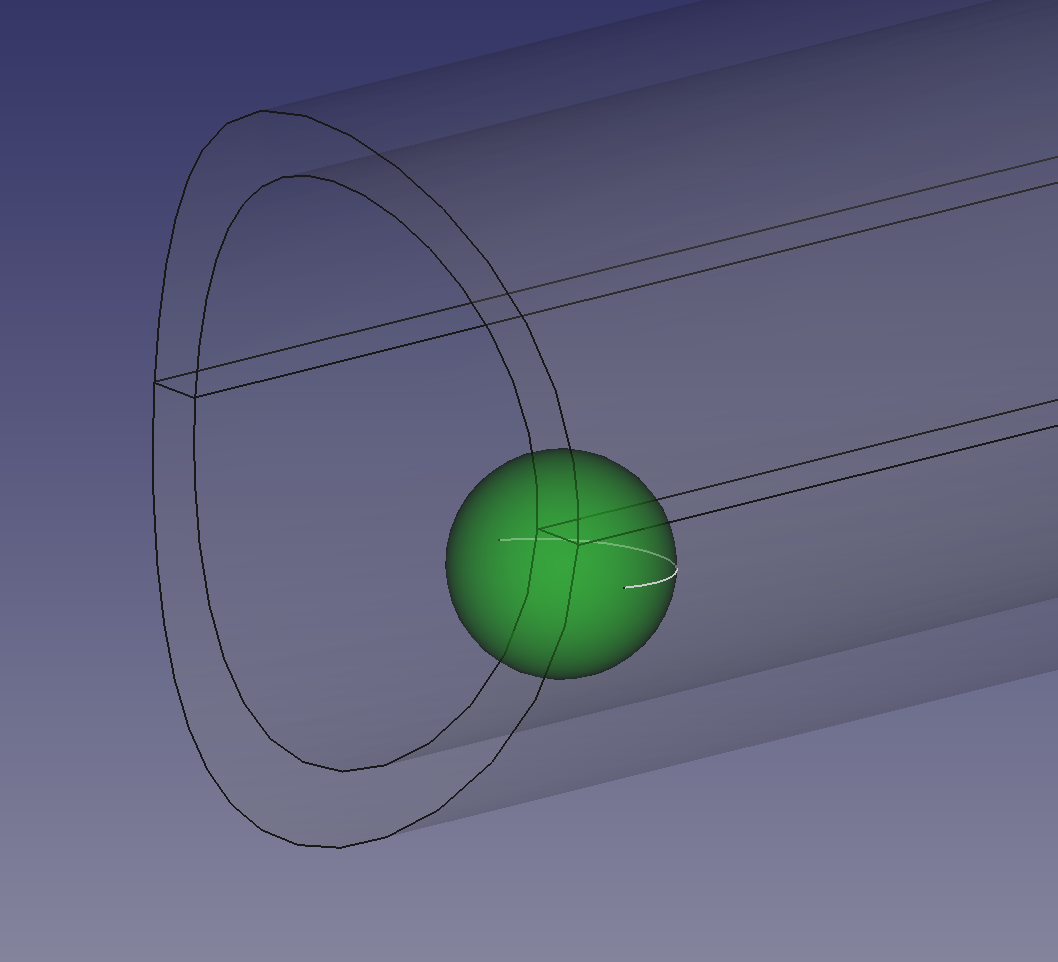
A file called intersect.pos is produced which contains four (not six) sets of co-ordinates, all of which are within a couple of millimetres of each other. If I go and look at the CAD data at that location (marked with the ball in the screen grab), it’s really not looking like a clear and present danger to the fabric of society.

Or here if the link is broken Why are my links always broken, by the way? The images display fine if I paste the URL into a browser.

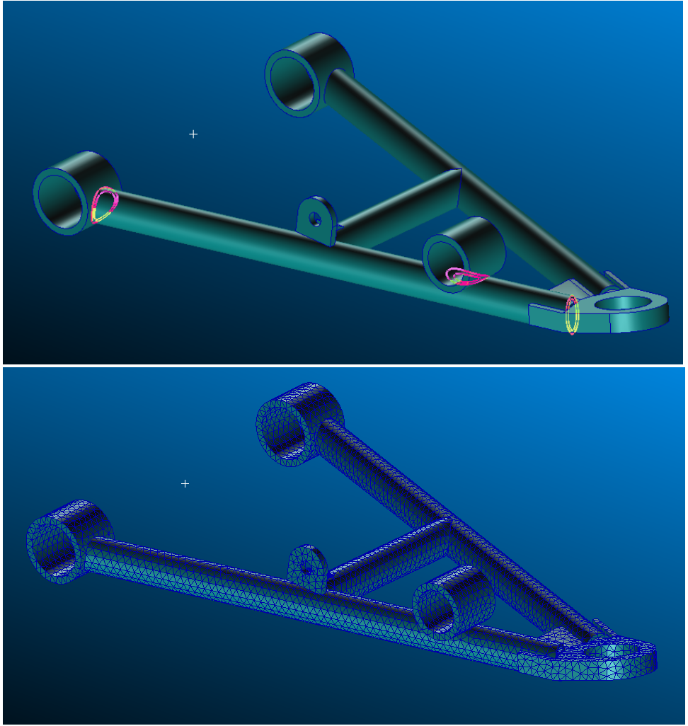
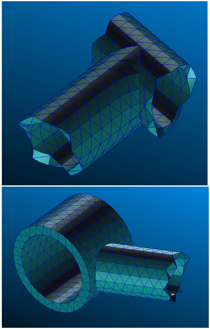
It’s clear when I look at the surface mesher that it has got its knickers in a twist in this area, with all sorts of sliver elements that are clearly foxing itself. It’s really not clear to me why it would do that, specifically. Especially since on a nearby tube which is pretty much identical in this area, that tube meshes just fine.


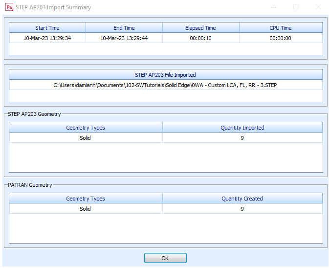
On the other matter, I read in the FreeCAD model with the shell mesh. I’m a big fan of shell meshes, as evidenced by the effort I went to, to make one as described in the last post on this thread.

The “Results Mesh” that arrives in LowerArm_2_2Dmeshed_cleared is very different to the mesh in the posted GIF. The model is also full of things I didn’t put in it, like “FaceBinders” (6 of those), surfaces and sketches. It’s not apparent to me how to get to a surface mesh even from this model; I only seem able to mesh individual tubes and as I know already I can’t have multiple mesh objects in a single analysis.

But like I said, I am somewhat obsessive about the original question.

How do I know what to fix if my CheckGeometry tells me everything is fine, and when I dive into the detail as described above I can’t really understand what’s wrong with the geometry?

I don’t really believe that recreating the geometry every time is the answer. I was doing that 30 years ago in Patran 2.4, but I think we should be past that now. Patran 3, SDRC I-DEAS and Hypermesh were all about using native CAD data for productivity and were firmly established by the late '90s.

And I can’t resist commenting that this is the finite element method, with the emphasis on finite. The truth, in my domain (vehicle suspensions), is that we never really know what the load conditions will be, we never really know what the material is (weld toe metallurgy, anyone?) and the welds themselves are never some geometrically perfect item in any case. The analysis an approximation, to get us to something worth testing. So the outcome from all this for me, for this and multiple other components, is one of three things - “It needs more metal here and here”, “It’s about right” or “we can take weight out here and here”.

It’s only part of the whole journey I’m trying to make. It should be obvious from these posts that I don’t expect not to put some effort in, and it should be obvious from these posts that I don’t expect everything to “just work perfectly”. I am trying to get help with this particular toolset. As far as I can tell I am asking the right questions.

So, again, how do I know what to fix if my CheckGeometry tells me everything is fine?

It’s also clear that if I offer the same information to Patran 2021 - which is available to me for educational purposes, but not for officially completing this activity - that Patran identifies the original file as containing 9 solids and nothing else:

Or here if the link is broken

The geometry reads in cleanly and meshes cleanly:

Or here if the link is broken

In the problem areas, with some sensible mesh parameters, it manages very sensibly:

Or here if the link is broken

What conclusions am I to draw from this? Difficult to say. But it’s surely hard to argue that the originating data is flawed. Much more likely that I am making errors in a tool unfamiliar to me. Which is why I am here.

To get help avoiding these errors.

So what am I missing?

The best reply I can do: https://devtalk.freecad.org/t/how-to-check-where-negative-jacobina-are/43813/6

I don’t really believe that recreating the geometry every time is the answer. I was doing that 30 years ago in Patran 2.4, but I think we should be past that now. Patran 3, SDRC I-DEAS and Hypermesh were all about using native CAD data for productivity and were firmly established by the late '90s.

Sure, so 30 years later Patran 2.4 is open source and for free, and it’s named FreeCAD FEM workbench, not so bad after all :wink:

And I can’t resist commenting that this is the finite element method, with the emphasis on finite. The truth, in my domain (vehicle suspensions), is that we never really know what the load conditions will be, we never really know what the material is (weld toe metallurgy, anyone?) and the welds themselves are never some geometrically perfect item in any case. The analysis an approximation, to get us to something worth testing. So the outcome from all this for me, for this and multiple other components, is one of three things - “It needs more metal here and here”, “It’s about right” or “we can take weight out here and here”.

I see your point, you would like a kind of multi-meshed model, with rigid links between sub meshes for eg.
Of course such approach would allow to work with non continuous models, non continuous mesh. But FEM WB doesn’t handle multi-meshes for now (except in bernd experimental github branch IIRC). Hence IMHO you have to fine tune your mesh, that’s mandatory to get a reliable single mesh then good results.

Why are my links always broken, by the way? The images display fine if I paste the URL into a browser

I don’t know, it should work with

tag :confused: It’s seems you do the right way, I don’t get the issue.
Humm, maybe you paste the URL but you forget to load the file on the forum? Do you load it with Add files button in Attachment section below to the screen?

Yes, maybe TIE contact constrain could be a way to get what you want on raw model made from weld elements. But it will not fix bad topology of sub-bodies by magic.
I’m gonna try to send an example, on moment please.

Not every time but in this case you should do that. :wink:
The geometry is impossible to manufacture and impossible to assemble.
A: equal tube diameters, tangential contact at the outer surface. Impossible to cut the tube like this.
You can mesh this as much as you want, you will allways get distorted elements in the tip of the cut.
B: the cube inside the tube blocks the assembly.
Why should gmsh be more intelligent than the CAD-technician?
Anyway, maybe a good meshing exercise.
impossible-part.JPG

For sure :mrgreen:

So, here is an example of 2 cylinders with gap between.
With Tie constraint you can merge distant nodes (it involves local stress).
Such strategy allows to analyse a non continuous single mesh object, with gaps between solids:
Tie_constraint_2_cylinders.gif
FC-FEM-Tie-Const-gap-cylinders.FCStd
But this strategy doesn’t fix topological issue, bad tangencies, null thickness, tiny inner gaps, tiny shapes, etc…
I can’t mesh your LowerArm model with this approach because of the too bad topological quality.
As thschrader said:

Why should gmsh be more intelligent than the CAD-technician?

I agree, with FC FEM you can mesh a lot of things, but not anything.