Hello,
It could be very useful if techdraw were able to copy Edge/Lines colors from the 3Dview to retreive it in generated views, and also set this color when you do a dxf export !
The best should be to detect Draft.Layers and create them in the view->dxf export
It is very important when you do architecture/building plans, to separate parts by layers or colors.
In other way, TechDraw could provide python functions to retreive an array of hidden lines coordinates, and one array of lines by Shapes converted
I tried to read the cpp code from TechDraw but I’m unable to do that, it’s too hard for me.
French:
Cela pourrait être très utile que TechDraw différencie les couleurs de pièces attribuées dans la vue 3D, et que ces couleur soient exportées au moment de l’export dxf d’une vue.
Le top serait que techDraw arrive à détecter les Layers créé depuis Draft, et qu’il les appliquent au moment de l’export dxf tout en séparant les lignes cachées dans un autre layer…
Ou alors, si TechDraw pouvait avoir des fonctions python d’accès à un tableau contenant les lignes cachées générés, et un tableau de lignes par objets générés, on pourrait faire des merveilles ! on pourrait avec ces fonctions sur un export dxf séparer les éléments dans des calques distincts par exemple !
Je n’ai rien trouvé à ce sujet
pourquoi cette requette : Dans mon domaine, j’utilise des cotes cumulés par exemple, pour la fabrication de murs ossature bois. Je suis donc obligé de passer par un export dxf pour travailler mes plans. J’ai des cotes d’altitudes, et j’en passe. Je travaille beaucoup avec les épaisseurs de traits, et sans export dans des calques séparés c’est impossible
Hello I’ve made some screenshots :
Here is my 3D view :
if I generate view I have good hidden lines job ! but no line color :
Finally if I export to dxf, this is what I have, only one layer called “view”, no hidden lines separation:
And know I’ve made a script with dxf layer creation :
import ezdxf
from ezdxf.tools.standards import linetypes
import FreeCADGui,DraftLayer
import Drawing
import TechDraw
from pivy import coin


#Select all objects
for sel in FreeCAD.ActiveDocument.Objects:
	if sel.ViewObject.isVisible():
		FreeCADGui.Selection.addSelection(sel)

obj= FreeCADGui.Selection.getSelection()

# Detect Draft Layers in selection
layers=[]
for i in obj:
	#print( i)
	if hasattr(i,'Proxy'):
		if type(i.Proxy) ==DraftLayer.Layer:
			layers.append(i)


#DXF CREATION
doc = ezdxf.new(dxfversion='R2010')

####Create layers in the DXF
for i in layers:
# Create new table entries (layers, linetypes, text styles, ...).
	doc.layers.new(i.Label, dxfattribs={'color': 2})
	l=doc.layers.get(i.Label)
	col=i.ViewObject.ShapeColor
	#Conversion float to RGB
	r=col[0]*255
	g=col[1]*255
	b=col[2]*255
	l.rgb =(r,g,b)

##add hidden lines Layer
#add hidden line style
doc.linetypes.new('HIDDEN', dxfattribs={'description': "Hidden _ _ _ _ _ _ _ _ _ _ _ _ _ _ _ _ _ _ _ _ ", 'pattern': 'A,6.35,-3.175'})
txt_hidden="Hidden lines"
doc.layers.new(txt_hidden, dxfattribs={'color': 3})
l=doc.layers.get(txt_hidden)
l.dxf.linetype = 'HIDDEN'

####TODO
#### copier les éléments et les remettre sur un plan XY
#### analyser qui est devant et qui est derrière
#### séparer les lignes lorsqu'ellessont à moitité caché (chaud)


### start modelspace
msp = doc.modelspace()
### Now try to extract lines
#select shapes in layer

doc.layers.new("TESTS", dxfattribs={'color':13})

for lay in layers:
	print("Select shapes in layer:",lay.Label,"\n")
	group=lay.Group
	for part in group :
		if hasattr(part,"Shape") :
			for l in part.Shape.Edges:
				#get vertices of edges
				start=l.Vertexes[0]
				end=l.Vertexes[1]
				msp.add_line((start.X,start.Y,start.Z),(end.X,end.Y,end.Z),dxfattribs={'layer':lay.Label})
doc.saveas('test.dxf')
this is what it generate, all layers are created, but I’m unable to calculate and separate hidden lines… :
Édit: I think i have to work with viewobject, and not Shapes object…
Hidden lines are calculated by the OCC Hidden Line Removal (HLR) algorithms. Once a shape passes through HLR any connection between Edges in the source and Edges in the result is lost. So there is no way of knowing what appearance attributes in source belong with which object in the result. In addition, the face detection logic has to break some Edges into pieces.
There are special cases where this is possible - ex Sketches don’t need to have hidden lines removed so there is a 1:1 correspondence between source geometry and result geometry and Sketcher appearance attributes could be carried over to the drawing.
So i think there’s a way to make it up.
First : I would like to retreive shape’s lines in 2d (exactly has shown in 3dview), techDraw does, so why not me ?
retreive once with shaded ( hidden line not shown) HLR ?
retreive twice with all lines .
try to find intersections between hidden and not hidden → remove doubles → separate hidden lines → and to finish separate visible lines in different layers.
I’m unable to retreive 2d coordinates of shown shapes like teckDraw does.
Where I Have to find ? in Gui.ViewProvider ? in coin ?
Is HLR accesible in python ?
Do you think it’s possible to combine HLR, with another extraction method and compare/merge the two results ??
Ok,
wandererfan(thanks):I probably know how hidden lines are calculated. It use OpenCasCade, yes ?. And now, How do you pass Shape in OCC and retreive result in python ?
My way should be(probably) to pass, shape by shape and compare the result with all shapes passed with HLR algo.
I think it’s not impossible, we just have to send more OCC calculations and merge/compare them.
I just want functions to export my shapes viewed in 3D in OCC functions/doc to start my tests.
I don’t know how to do … it’s frustrating
Note that with recent 0.19 versions, if you use the Draft view, it now has an option to keep original line width/colors/style. This gives pretty faithful autocad-like sheets…
But Draft views don’t work for 3D of course… One solution for 3D is to use the Coin view feature of Arch views. Not sure line colors are working though… Needs some testing
arf,
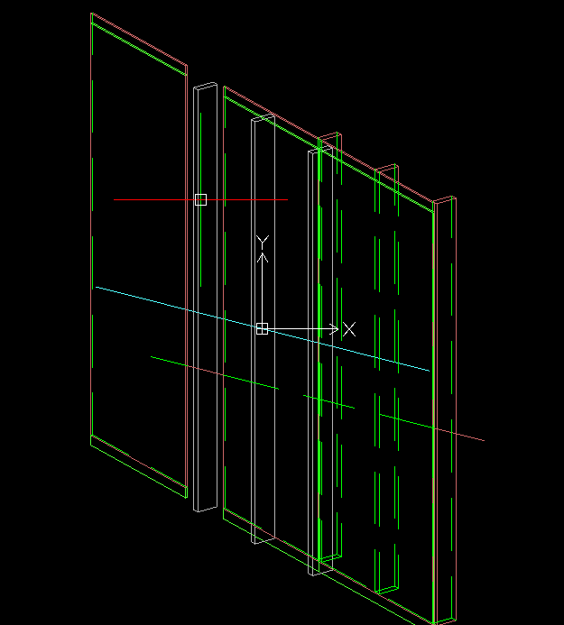
Just a small problem. if I Extract Layer by layer, the projections haven’t got the same coordinates
in red : all the model
in green dashed : hidden lines
in other colors, the layer separation
do I have to pass an argument to the TechDraw.View object ?
this seems that the view is centered on the selected objects. I think that if I create a bounding box(a container) of my render, all my layers will have the same coordinates, isn’t it ?
I’ve worked on it today.
this is the source :
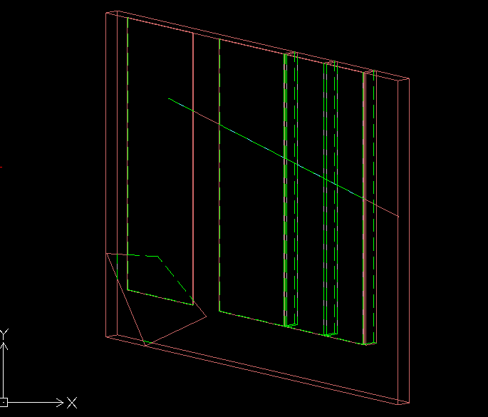
Now I Have layers aligned by creating bounding box:
here is the model exported with “temp” line in red :
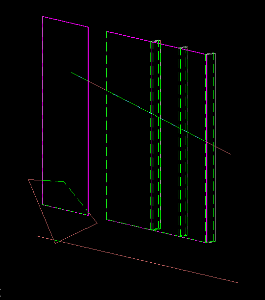
and if I hide “temp” layer:
Now I have to suppress doubles, remove the bounding box, and the hardest point, color splitted lines
EDIT: after remove doubles
Is there a function to test if edges are collinear ? I will have to test that to color splitted lines
I’ve to rework on bounding box lines, they have to be more small to not much interact with the render
from WFrame import WFDxfExport

export = WFDxfExport.DxfExport(Gui.Selection.getSelection())
export.extractLayers()
export.extractModel()
export.save()
You have to select objects and layers you want to export before launch
(sorry I haven’t made security to launch with no selected objects at the moment !)
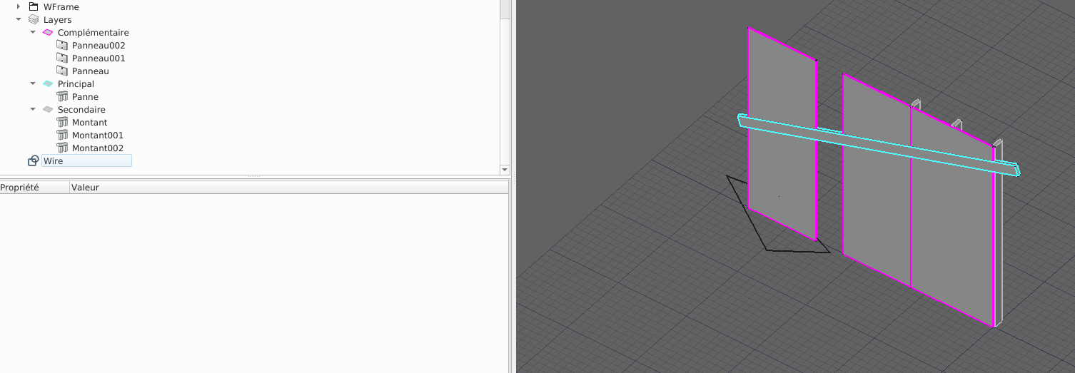
this is the source :
and this is the result in draftsight :
I’m very very happy
They are some mistakes but it’s quite good !
update my github workbench if you want to use it.
I’ll make button and dialog taskbox to use it in few days
I think this tool has not his place in draft, but more probably in arch. I’m trying to make functions to use it easly, so I will post discussion after the tool will be released.
It will probably work for draft objects too !
EzDxf is a python library/package(MIT licence) that provide good functions to create/write dxf files. A member told me it’s existance, and I tried. https://ezdxf.readthedocs.io/en/master/
Just for reference, Arch is built on top of Draft. Arch actually uses the Draft routines to export DXFs and do many other things, so that’s why I suggest adding the code directly to Draft.