I use freecad probably everyday both for my job and at home for my house project.
I start use around 0.15 version without posting anything as i normally find answer on forum.
But today i can’t…so lets try to ask you.
I want to estimate a deformation under pressure of a box. This is a quite simple problem
As you can see the deformation is around 9.14mm. A real life trial give me 8mm. (perhaps it’s not so bad for FEM)
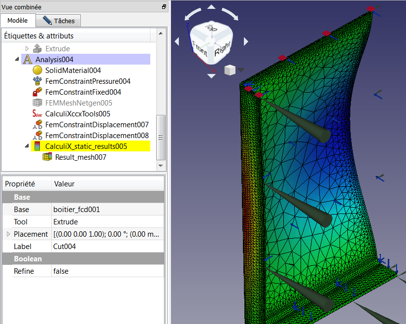
Then i cut my part to decrease mesh size and time for calculation
Then the deformation is 12mm.
Question 1 : How do you explain this difference ?
I want to add a cover to see also the deformation
Question 2 : How i can fix one point (it’s seem to me that i doesn’t work)
I suppose, that the mistake between real life and FEM is due to nonlinear simulation (aluminium material)
So i try to set nonlinear geometry to true. I give some strange result.
Sometime i have just one result with quite acurate results and some time i have several time step. the last one is not so bad.
Question 3 : How ot set up non linear material ? Is aluminium non linear ?
Question 4 : what’s is the difference between linear and nonlienar ? should i look in calculix documentation ?
Question 5 : Is there a bug ?
Thanks a lot for the great job you do with freecad.
OS: Windows 7
Word size of OS: 64-bit
Word size of FreeCAD: 64-bit
Version: 0.18.14959 (Git)
Build type: Release
Branch: master
Hash: ff05101b68dc9a7d1e70dd69544f14ac8598a433
Python version: 2.7.14
Qt version: 4.8.7
Coin version: 4.0.0a
OCC version: 7.2.0
Locale: French/France (fr_FR) box_under_pressure_no_mesh.FCStd (57.1 KB)
If i understand well : When you have a symetrical plane, you need to block rotation on the other axe.
But what do you mean exactly when you add “(translation and rotation)” Did you only describe delflection ?(My english find its limit)
Now, i try to answer to other questions. But i haven’t find yet.
I remark that the last step of a non linear simulatione give value near real result after pressure test.
I don’t understand why. Do you have an idea.
Rotational degrees of freedom need to be set properly for symmetry BC for beam and shell element_s. In ccx, solid elements do not have rotational DOFs, so if you run UR’s example you will get exactly same results as if you let rotations to be free at boundaries.
try to imagine solid elements on the boundary - rotations are constrained since solid elements have 2 nodes through the “thickness” on the boundary cross section. Whereas shell element has only 1 original node on the boundary cross section curve, so you need to prescribe the rotation constraints.
The non-linear analysis calculates several iterations and after each iteration it updates loads acting now on the deformed mesh (and material if you define non-linear material properties). Thus it is more precise in case of large deformations.