Hi All,
I just came back to the FreeCAD Path workbench after being away for a few years. I’m super-impressed with how it’s looking – thanks to all who’ve been working so hard on it!
Today I’m struggling to figure out what the best approach is to mill my part (using a vertical CNC mill). I have a complex pocketing problem and I’ve tried a variety of operations but they all seem to want to ignore the various flat lands and the holes in the pocket. I suspect I’m choosing the wrong Base Geometry for the operation (or perhaps the wrong operation?).
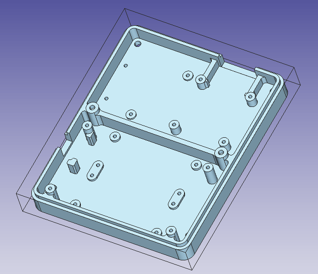
Here’s the part I’m working on (.step linked below):
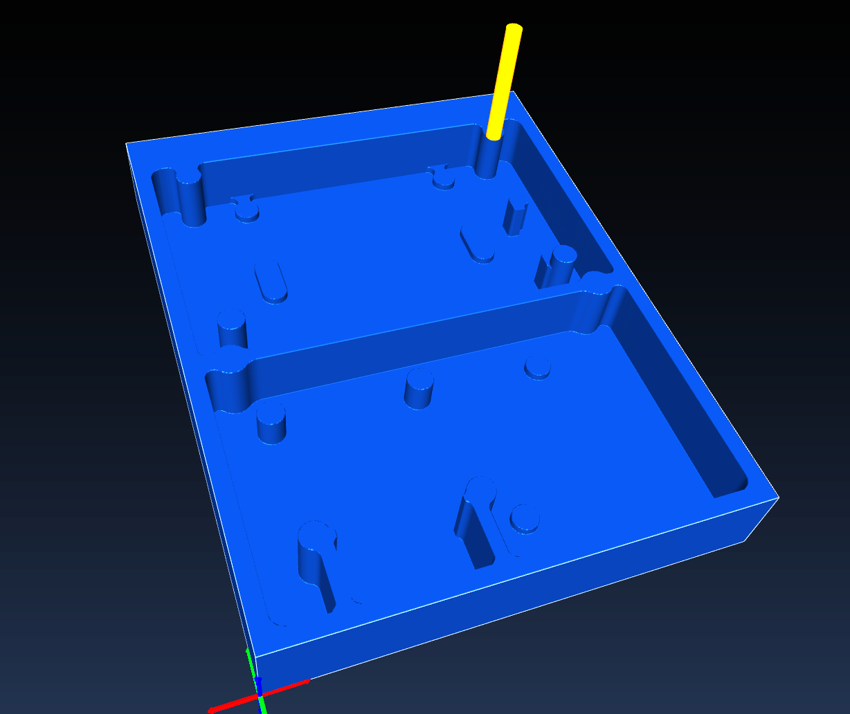
Here’s an example of a path that isn’t working out well since it’s avoiding the holes in the part:
What’s the best approach and combination/order of operations to finish a part like this?
Here’s the part I’m working on if anyone wants to take a quick and dirty shot at it for me: BaseV1A_V2.step (367 KB)
Thanks!
-Bill
My version info:
OS: Ubuntu 18.04.3 LTS (XFCE/xubuntu)
Word size of OS: 64-bit
Word size of FreeCAD: 64-bit
Version: 0.19.
Build type: Release
Python version: 3.6.9
Qt version: 5.9.5
Coin version: 4.0.0a
OCC version: 7.3.0
Locale: English/UnitedStates (en_US)
Hi Bill,
OK, thats not to do with an “one click Operation”…
For the holes use the drilling OP.
With 3D Pocket you gets the different levels of one pocket done if you select the lowest face, but it dos not work "outside of this face. For that you have to do seperate 3D Pocket ops for other areas. Base V1A_herbk.FCStd (140 KB)
Thanks – that’s super helpful and gets me started! I think I actually got to this point with 3D Pocket first thing and then got sidetracked trying to find another operation which would handle the whole part…
I’m always amazed by what ppl are doing with FC in general and Path specifically - very impressive.
Assuming you use a PocketShape operation you can use the Extensions to cover up those holes. Having said that, it would be a nice feature if PocketShape had direct support to mill over holes.
Thanks chrisb! I really wanted to mill those lands – so I’m not sure how to get MillFace to handle it?
mlampert – thanks! I found the Extensions option in PocketShape and played around with it – although I’m not sure I completely understand what it does? When I chose the bottom of one of the pockets plus the lands in the pocket as the Base Geometry for PocketShape and enabled all the extensions then it did cover the whole area but it stopped at the height of the lands – so I’m sure that would work with a second operation to finish the bottom of the pocket.
So, I think either PocketShape with extensions, or separate 3D Pocket operations will work!
This works yes. But my initial reaction is claiming utter heresy!! Face milling should never be the option to mill a complex pocket. Either a pocket tool should perform the operation adequately or the mill face tool should be renamed at once! This is unacceptable.
It is a perfectly acceptable workaround.
But i stand by my initial reaction. Something just doesnt feel right here.
me to…
Bill didn’t ask for milling over holes (if i read the entire post correctly), his problem was, that pocket leaves all material above the higher sections around the holes up to the top.
But, btw:
This part of an case would be a good “test case part”. Bill will run in some more probs if he wnt to mill the outside and the top of the wall with it’s “fitting step”.
At the outside of the step would be needet the posibility to mill a not closed loop edge, at the top of the wall and the step needs the posibility of the use of a tool which has more diameter as the with of the face to mill…
This is not a complex part to pocket just a very tedious 2D tool path. Nothing about this part is 3D Surfacing what so ever. There are a lot of ways to do this job. There are a lot of things to consider. It is a pretty straight forward task. I have attached some amusing possible cuts with an 1/8 endmill just for fun. Check out my PathWorkbench tutorials for more details on the techniques used when dealing with 2D patterns. https://forum.freecadweb.org/viewtopic.php?f=36&t=41781https://forum.freecadweb.org/viewtopic.php?f=36&t=41877
Note the first tool path goes over the entire inside of this pocket. This you would take to your first depth.
This picture shows the tool path going around the 4 posts in the pocket and over 2 of the smaller ones. This tool path would be taken to the next depth. and your final tool path would go around all the post inside the Pocket. Of course I had to do some reversing to get the sketches I wanted from this model but it is all part of creating well thought out tool paths that do what you want and only what you want.
Freecad file these screen shots were snagged from. I will admit this was 30 mins of my time not including posting this. Example.FCStd (253 KB)
Another example using just the Pocket from face tool in the PathWorkbench
And the Example file that goes with the above picture Example.FCStd (617 KB)
I just had some time to look into the model.
There is no shortcut to this task.
In my opinion:
Face milling of each Drilled Post. With adequate positive “material allowance” value to make sure you make a nice platform there.
Drilling of each hole.
3.Then normal pocket milling of the bottom.
Why first facing: to produce a nice flat platform for drilling.
Why then drilling: because drilling on supported surface (not yet a milled post) is more rigid.
Why pocket milling at the end, so that the posts are generally shorter (so more rigid) and it makes clean cylinders.
There are no two ways about it, for some of this you’ll have to use a small small tool.
----to note: it is completely wrong to call the option “material allowance” in the Face Milling tool, that is not how a facing operation works, most of the times you want to overshoot the whole face (fly cutter, large flat end-mills, clearing burrs…etc). So technically it should be “over shoot” by default or the adequate milling linguo for the overshooting. “Allowance” would only be true if using negative values of this parameters, that’s when material is intentionally left untouched . Only in that case does “Allowance” make sence as a term. Perhaps a drop-down menu in the Face Milling tool saying “allowance” or “overshoot” with the editable value with only positive values accepted.
This seems sensible to me. I would probably use an adaptive roughing op to do the bulk of the clearing and then use profile operations to bring the part to final size.
If you machine this part please can you post some photos?
I’m getting some nice results using multiple Pocket_3D operations.
Here’s an intermediate result displayed in Camotics:
Quick question: Is there a way to force an operation to use the results of a previous operation as its starting point? (In other words, I want to keep operation #2 from milling areas that were already removed in operation #1).
Ouch – that hurts! I’m starting to understand some of the suggestions above (some of which seemed pretty involved). Is the limitation in the simulation? Has anyone tried using (manually operation-by-operation) Camotics to bridge that gap?
I don’t think so. Such optimizations are currently mada manually by adjusting the depth parameters, and by using the profile operation which doesn’t touch the innards of a pocket.