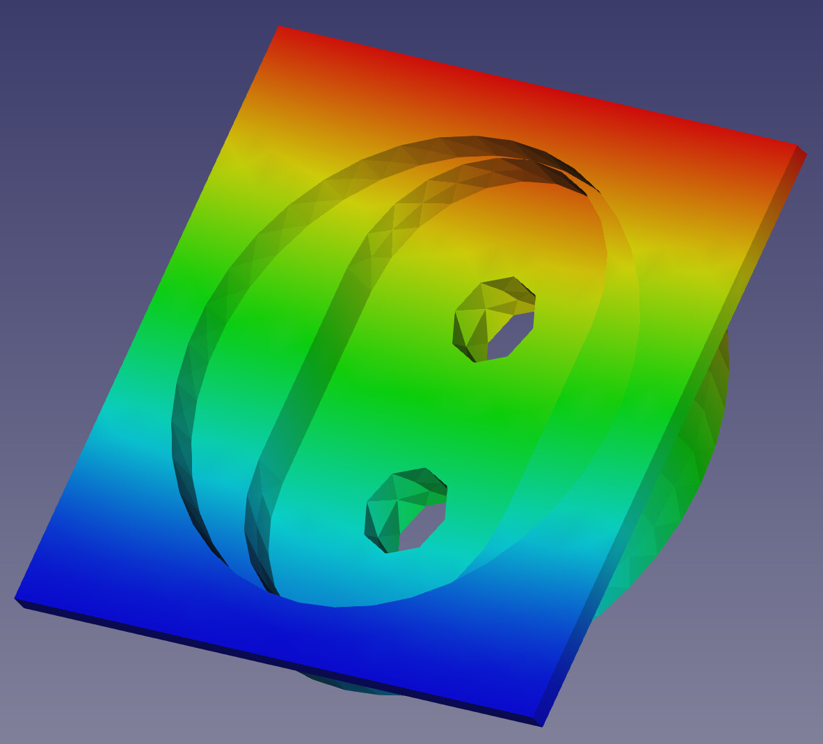
So I keep getting this error in some models persistently, and I have now an eye for identifying why. However I still don’t have a good way to resolve the problems. https://forum.freecadweb.org/download/file.php?mode=view&id=144462
In this case, there seem to be a cylindrical surface tangent to another surface. My guess is that the triangulation tries to continue with flatter looking triangles until it can no longer do so. Probably the surface turns inside out or something at a small scale and that’s where the error comes from?
No idea. But I know that if I remove that feature, then my analysis will probably run. I am wondering if there is development in GMSH or netgen or calculix to somehow fix this problem. maybe by giving the user suggestions on how to fix it or identifying the problem in the mesher and changing the parameters some how?
its pretty simple geometry that originally came from solid works. I just cut off most of it to focus only on the important area where it just won’t mesh. test-Body001.step (78.3 KB)
The non-positive jacobian is quite a common problem with Calculix. Calculix is quite rigit when it comes to non positive jacobian.
maybe that we have to dive into the problem as forum. i have quite often that GMSH don’t have non positive jacobian but calculix have.
As far as i know there isn’t any information on the wiki.
Maybe add a known calculix problems on this page: https://wiki.freecadweb.org/FEM_CalculiX
Maybe including what the steps needed te deduce the risk
site note imple search on non positive jacobins in the first 3 results are 2 FC related…
Now that’s interesting. Using the same GMSH that is supposed to be used by freecad, I get no errors about jacobians. I basically exported the step file that I attached here earlier, then opened it in GMSH, I took the defaults but changed the mesh size to max 1mm and hit the 1D,2D,3D mesh buttons. Exported to UNV and imported that into freecad. Not only was it really fast, but no jacovian errors.
So I don’t understand what is happening. why does getting the mesh from GMSH in freecad take way longer? Why do i still get the jacovian errors using GMSH from freecad but not manually? very weird. Is there a settings file that everyone is using which I don’t know about or something?https://forum.freecadweb.org/download/file.php?mode=view&id=144470
I think the creation time is probably the same. but FC reads the mesh in(python) while creation all done is in i assume C / C++. I don’t know if the FC read can be speed up.
When writing it again for CXX is another time consuming layer.
Then as last probably the most weird step. i thought i had read somewhere that calculix does something with it. and i have no clue why
BTW:
there should be no difference between gmsh in FreeCAD and stand alone gmsh, if exact the same paramter are used. You can even do what FreeCAD does … What the report console during meshing. The file path of the geo file is printed. Open this geo file with gmsh will do what FreeCAD does.
I have seen meshes without nonpositive jacobian in gmsh but ccx complains about non positive jacobians and the other way around. Gmsh complains about nonpositive jacobians and ccx does not.
The best what could be done are:
use a finer mesh
set the parameter Second Order linear to True in FreeCAD gmsh object
Ahh welcome to FreeCAD FEM
cheers bernd
We should may be start a wiki page about the nonpositive jacobians, as they are the most often seen problem in FEM which is sometimes not easy to solve.
How would I set the parameter that you mention below from freecad?
Here is a file with the FEM setup which is just there to have calculix run. https://forum.freecadweb.org/download/file.php?mode=view&id=144497
In the file I include a mesh that was created by the internal gmsh and another by the external gmsh. take a look. The internal one is only slightly different in how the triangles are arranged. test.FCStd (928 KB)
here is what the FreeCAD gmsh call for your mesh is look like. As said it is the geo file printed in the report console
// geo file for meshing with Gmsh meshing software created by FreeCAD

// open brep geometry
Merge "/tmp/fcfem_1di6hlgg/Body001_Geometry.brep";

// Characteristic Length
// no boundary layer settings for this mesh
// min, max Characteristic Length
Mesh.CharacteristicLengthMax = 1.0;
Mesh.CharacteristicLengthMin = 1.0;

// optimize the mesh
Mesh.Optimize = 1;
Mesh.OptimizeNetgen = 0;
Mesh.HighOrderOptimize = 0;  // for more HighOrderOptimize parameter check http://gmsh.info/doc/texinfo/gmsh.html

// mesh order
Mesh.ElementOrder = 2;
Mesh.SecondOrderLinear = 0; // Second order nodes are created by linear interpolation instead by curvilinear

// mesh algorithm, only a few algorithms are usable with 3D boundary layer generation
// 2D mesh algorithm (1=MeshAdapt, 2=Automatic, 5=Delaunay, 6=Frontal, 7=BAMG, 8=DelQuad)
Mesh.Algorithm = 2;
// 3D mesh algorithm (1=Delaunay, 2=New Delaunay, 4=Frontal, 5=Frontal Delaunay, 6=Frontal Hex, 7=MMG3D, 9=R-tree)
Mesh.Algorithm3D = 1;

// meshing
Geometry.Tolerance = 1e-06; // set geometrical tolerance (also used for merging nodes)
Mesh  3;
Coherence Mesh; // Remove duplicate vertices

// save
Mesh.Format = 2;
// Ignore Physical definitions and save all elements;
Mesh.SaveAll = 1;
Save "/tmp/fcfem_1di6hlgg/Body001_Mesh.unv";


// **********************************************************************
// Gmsh documentation:
// http://gmsh.info/doc/texinfo/gmsh.html#Mesh
//
// We do not check if something went wrong, like negative jacobians etc. You can run Gmsh manually yourself:
//
// to see full Gmsh log, run in bash:
// /usr/bin/gmsh - /tmp/fcfem_1di6hlgg/shape2mesh.geo
//
// to run Gmsh and keep file in Gmsh GUI (with log), run in bash:
// /usr/bin/gmsh /tmp/fcfem_1di6hlgg/shape2mesh.geo
ATM it is only you who knows what mesh parameter where used in gmsh on manually meshing.
BTW:
If “Second Order linear” is set to True in Gmsh mesh object in FreeCAD there will bi no nonpositive jacobian.
might be this is set to standard in manual gmsh run?
A mesh region does not help either … the problem resist on the same place. It is because the edges results in zero distance but gmsh does not repect element sizes on this. Netgen is much better here.
But as said I would just use Second order linear parameter and use no mesh region in this case.
but how do I set the order to second order from freecad??? I think I know where to do it on GMSH manually, but not on freecad
“Second order linear parameter”
Hello, I’m trying to rejuvenate a 3 year old thread that had a few gems.
Bernd, or anyone else who knows this.
Care to elaborate on that one-liner please?
I’m also stuck with some nonpositive jacobian determinants and would love to get at the culprit surfaces. My model is large at 60x30x20 feet and I’m meshing in the 20 to 50mm region
I don’t get which “Run” button is being referred to in the post above. I’ve rather patiently visually scanned the whole mesh once it has been generated with errors. Never found surfaces highlighted like the image above. Trouble shooting will be a breeze if I can have this option working for me.
Thanks in advance.
Gmesh 25-1 mm 1st order.png
OS: Windows 10 build 19045
Word size of FreeCAD: 64-bit
Version: 0.21.1.33668 +26 (Git)
Build type: Release
Branch: (HEAD detached at 0.21.1)
Hash: f6708547a9bb3f71a4aaade12109f511a72c207c
Python 3.8.10, Qt 5.15.2, Coin 4.0.1, Vtk 8.2.0, OCC 7.6.3
JWorks Bernd is not active here anymore. Negative jacobian locations will be highlighted when you try running the analysis using the default solver FEM SolverCalculixCxxtools and FEM SolverRun button.