Hi, whilst thinking about how ArchWall can support different curve in separate thread, I test to output a model with below and find ArchObject extruded based on Sweep not working (yet) - PartExtrude OK.
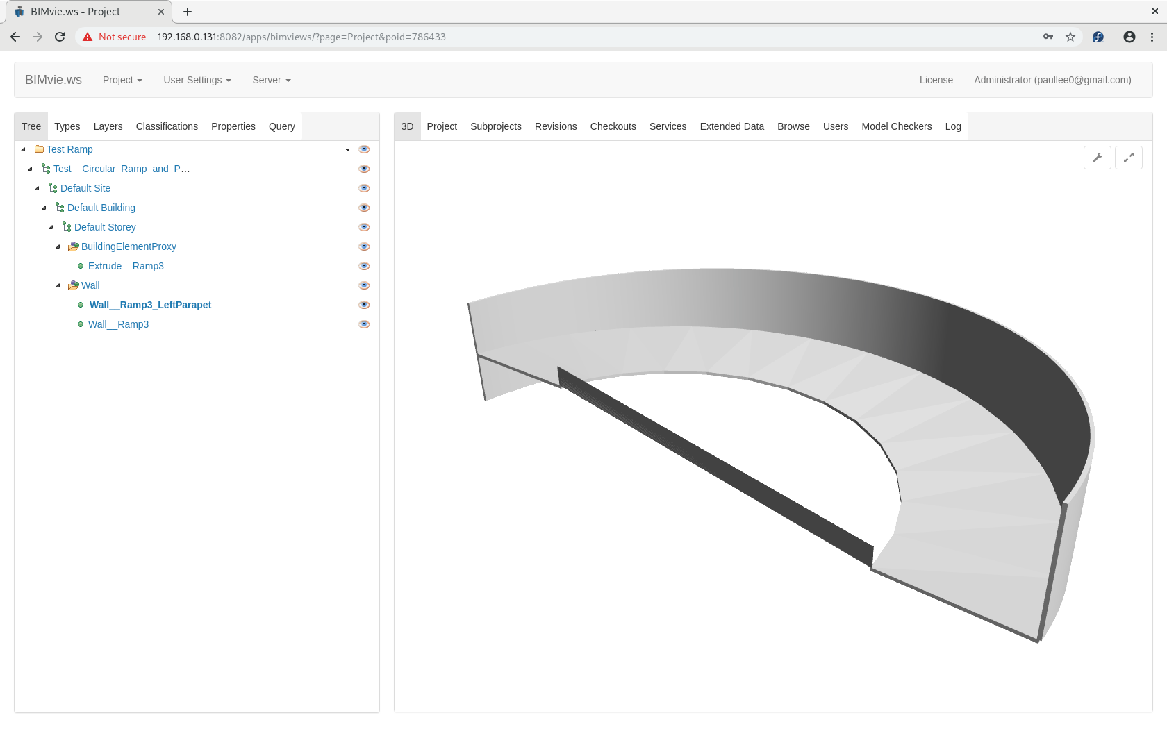
3 Objects - ArchWall Extrusion based on Sweep Not OK on IfcExport
ArchWall on Arc - OK on IfcExport
Sweep on 2 straight Edges, at different height, along a Arc path form a Surface; Part Extrude the Surface to Solid - OK on IfcExport
(Part Extrusion labelled - Extrude__Ramp3)
Sweep on 2 straight Edges, at different height, along a Arc path form a Surface; ArchWall (Structure same result) to Solid - IfcExport Not OK
(ArchWall labelled - Wall__Ramp3_LeftParapet)
FC 0.18_pre
on Fedora 29
FreeCAD_0.18.16079_Conda_Py3Qt5_glibc2.12-x86_64
p.s.
The ifc viewed slightly different on BIMserver BIMvie.ws, IFC++, re-open by FC … separate story (BIMvie.ws / FC seem better the IFC++ )
I find it painful how you mix different items like Part objects with Sketches and then Arch objects on top.
Personally, I think you should either
create your geometry with Draft Workbench, and then use Arch Wall or Arch Structure to give it thickness and height, or
build your entire solid with PartDesign Workbench, and then add Arch on top.
The first works fine for simple walls made up of straight wires. The second is better for complex shapes.
I took your file and remade the shapes. I didn’t align everything properly but I hope you understand.
You are relying on the Arch Wall or Arch Structure to provide the thickness and height of your Wall. I don’t do that, I use the underlying features to provide the thickness and width. So the big, outer wall is just a Sketch, that is Padded, which is contained inside a Body. On top of this body, Arch Wall is used. If I need to change the wall, I can edit the underlying sketch, to change the shape and thickness, and the PartDesign Pad to change the height.
The smaller, inner wall is made of two sketches, which are used in a sweep, and then they are extruded to give them height, and then the Arch Wall is used on top. In similar way is the ramp created. The sweep creates a face, which is then extruded to create a height, and then Arch Wall is used on top. The last item is the same as the second, but the extrusion has a shorter height, and instead of using Arch Wall, Arch Structure is used.
This makes more sense to me, as you aren’t relying on Arch to create the shape of your wall; you create your shape, and then just logically assign it to be a Wall, or Structure, or Equipment, or any other Arch object. You should test whether this method produces an IFC file with the correct information. These walls have heights and thicknesses, but these values are ignored, and the underlying solid is used instead.
I would advice against using Part Workbench features. In your modelling, it is not evident how you create the Part Sweeps. You select the two Sketch profiles (“Sketch__Ramp3_ParapetBaseStart”, “Sketch__Ramp3_ParapetBaseEnd”), and then you select a sweeping path; however, this sweeping path is not visible in the tree view. This makes it hard for others, and maybe for yourself in the future, to understand how you created the shape.
Not every property of the Sweep is visible or accessible from the Tree View or the Property View. These values are however, accessible from the Python console.
# In your original file
obj = App.ActiveDocument.Sweep005
obj.Sections[0].Label # 'Sketch__Ramp3_ParapetBaseStart'
obj.Sections[1].Label # 'Sketch__Ramp3_ParapetBaseEnd'
obj.Spine[0].Label # 'Sketch__Ramp3'
obj.Spine[1] # ['Edge1']
This indicates that the sweeping path is “Edge1” of “Sketch__Ramp3”, which is used in another object (“Wall__Ramp3”). This is hard to trace, unless you are very familiar with your own model.
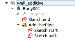
I suggest using the PartDesign Sweep (PartDesign AdditivePipe), with appropriate sketches as Profile, Path and Sections in order to parametrically create a sweep. You can double click this feature and modify which elements are part of it later on. This information is also available from Python.
In your file, the Sketches have very odd placement [-636 m, 166 m, 8.4 m], 41.2 deg rotation, for example. Personally, I think it’s better to encapsulate the Sketches inside PartDesign Bodies, and then you can move the entire Body, or the resulting Wall or Structure or Equipment or Roof, etc., to the position you want. If you aren’t using Bodies, then I suggest using Draft Wires, as Wires can be positioned exactly with the help of working planes, grids, and snapping. Test_Circular Ramp and Parapet_2_new.fcstd (77.9 KB)
Don’t call it “PartDesignNext” or “PDN”. That name was used during the 0.17 development cycle (two years ago) to distinguish it from the older 0.16 version. But today “PartDesignNext” is just called PartDesign; the documentation doesn’t use the “Next” name. If you use “Next” or “PDN”, you are going to confuse new users that are just getting into FreeCAD and don’t know the whole story.
The way current PartDesing works is what a modern CAD package like SolidWorks or Catia do, so it is a natural transition for many users. It has nothing “Next” about it.