Hello, I noticed the strange behaviour of the bezier curve tool:
the user keep adding points and the tool just create a big bezier curve, instead of splitting it into several segments.
I’d like it to work like this:
The behaviour in the gif is good but i think i broke the tool
soo… I investigated a bit ad i realized that the tool, when committing the creation of the curve dont give Draft.makeBezCurve the degree of the curve. If i’m able to fix also the preview i’ll start with this small fix that should improve the usability a lot i think
PS I’ve not finished with the editing tool, but i was searching for something to have fun and not thinking about it
without the Degree, Draft just create a single bezier segment, aumenting the degree with every node added. And i think this is not good and counterintuitive. Instead the user should set the curve degree before starting the creation and it should remain fixed for the whole curve.
The Draft Bezier tools creates for n points a bezier curve of degree n-1. You can change the property degree to get lower degree bezier segments in a next step
If you have 7 points and set degree to 3 you get 2 bezier segments.
with 10 points you get 3 bezier segments.
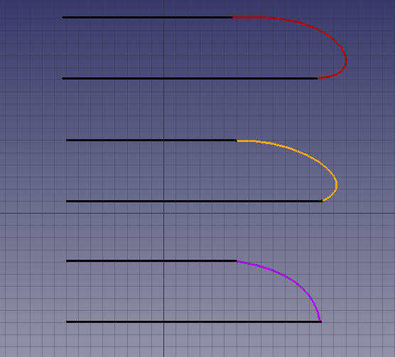
Here an example with teh same controlpoints anbd different degrees.
red is linear Degree 1
yellow is degree 3 - this is inkscape like.
OK, I think I understand now. Draft.makeBezCurve() in Draft.py is the low level code that creates a Bezier curve by calling the even more primitive Part.BezierCurve() function.
Then, the class BezCurve in DraftTools.py is the higher level code (user interface, button) that calls Draft.makeBezCurve().
without the Degree, Draft just create a single bezier segment, aumenting the degree with every node added. And i think this is not good and counterintuitive.
I also found this behavior a bit strange at the beginning, but actually… I think it’s not that bad. I don’t have a lot of experience using Bezier curves, but I think in most cases a user will use a curve to smooth or round a corner made of two other straight lines. In this case, what the user wants is to produce a smooth curve by clicking many intermediate points. So the more he or she clicks, the smoother the curve gets because the degree becomes larger. This is similar to how Draft BSpline works.
The degree of the Bezier is one less than the number of points, so if the user clicks 5 times, he or she will get a curve of degree 4, which is two end points and three intermediate points. I think in most cases, the user would not need degrees larger than 4, which is why quadratic (2nd degree, 3 points) and cubic (3rd degree, 4 points) Beziers are so popular in most drawing programs.
In this picture, from top to bottom, the two lines are tied with Beziers of degrees 4 (quartic), 3 (cubic) and 2 (quadratic).
Instead the user should set the curve degree before starting the creation and it should remain fixed for the whole curve.
I also find this comment on the code:
not quite right. draws 1 big bez. sb segmented
Do you agree?
I do think that having an option in the Task panel (DraftGui.py) to lock the degree of the Bezier would be good, as it gives more possibilities to the user. But how would the user use the tool, just a start point and end point? It would need two points?
If the order is three, and I put two points, the code would have to automatically create the two intermediate control points at an arbitrary location without regards for my preferred curvature. Then I would have to go back into edit mode to modify the control points to suit my needs. If the tool stays as it is now, I can more or less direct the curvature of the Bezier by how I place the points along a path.
What I wouldn’t like is to click many times on the 3D view, and that it creates multiple curves; that would be surprising. A single use of the tool should create a single object, not multiple objects. For example, if I use the Draft Wire, I want to get a single wire object, not many individual line objects; that’d just get messy in the tree view, you’d end with many, many objects in a short time.
Now, Draft already has a “continuation mode” to create multiple objects, one after the other. You activate this mode by pressing T in the keyboard (or checking the “continue” checkbox) after you enter the Task panel. That means that when you finish one object, it immediately starts creating a new object from the last point selected. So, basically, a Draft Wire is the same as a Draft Line with continuation mode on. It just creates line segments one after the other.
In your case, it would be like choosing (locking) the degree of the curve to 3, using continuation mode, then clicking two points; after the second point it would start creating a second curve, also of 3rd degree, and so on.
I think locking the degree of the curve is fine (with a checkbox and spinbox to choose the degree), but not breaking a high order curve into many objects, if the user doesn’t want to.
I do think that having an option in the Task panel (> DraftGui.py> ) to lock the degree of the Bezier would be good, as it gives more possibilities to the user.
+1
But how would the user use the tool, just a start point and end point? It would need two points?
i think we could provide two options:
cubic (fixed 3rd degree),
incremental degree (actual behaviour).
Keep in mind that the user can always change the degree of the curve after the creation, and this will affects the segment subdivision on document recompute.
I think locking the degree of the curve is fine (with a checkbox and spinbox to choose the degree), but not breaking a high order curve into many objects, if the user doesn’t want to.
Agree, i think the goal should be to obtain a single curve object with several segments (depending on how many points the user clicked and the curve degree)
Sorry, didnt see the response before. Of course you can. But that behaviour seemed odd to me, maybe i worked too much with inkscape in the last times… I’d like to draw it cubic since the beginning (eventually with drag and drop to define control points).
Letting of course the user decide if he wants keep using the current mode. What do you think?
PS I realized that i should change the name of the topic if everyone thinks that it’s acceptable like it is
I think this makes sense. The tool should create by default a cubic Bezier, as it’s probably the most used degree. But the user should also have the possibility of having the current system.
+1 … i already tried to but don’t think i can do it…
I think this makes sense. The tool should create by default a cubic Bezier, as it’s probably the most used degree. But the user should also have the possibility of having the current system.
I went on with the experiment to allow selecting the degree at the beginning of the bezier curve creation:
In the above gif i created 2 different commands, but they are exacly equal, they just differ from a different value set in the init:
. the first (old behaviour) have self.degree set to None
What I did to achieve this is just to copy the behaviour of _Draft.BezCurve to DraftTools.BezCurve and to DraftTrackers.bezcurveTracker, so they are more similar now.
I changed the creation command and the “bezcurveTracker” to accept the degee when drawing the curve. Everything seems to work to me.
Now I’d like to have your feedback on next steps:
the creation of the bezcurve is ATM incremental (the user keeps adding points), but I’d like the Cubic bezier to be drawn in this way:
. click to define the vertex (the point where the segment finish)
. drag to define the control point (all vertexes set to be SIMMETRIC so it’s smooth to draw it)
. release to create the segment
. going on like this for next segment…
so i decided to split the command in two instead adding a parameter.
the current BezCurve tool can be also implemented giving the user the possibility to change the degree while drawing the curve (HOW?).
fix the edit mode for multi segment bezier curves, since there we have something broken when the user try to edit a multi segment bezier curve (can you confirm?).
I’m submitting pull request 2523 so that the option Degree is in lowercase, degree. This is more consistent with the rest of the options in other functions in Draft and FreeCAD.
Pretty good!
I’ve been thinking a few about that tool:
I have to add a control because if you just click-release and not click-drag-release something doesn’t work good;
the tool should set the nodes continuity to simmetric, since it’s what it does at the creation, but they are not, they are just placed as simmetric;
for that i’d like to move some code that is inside draft edit into the new splitted DraftBezcurve, since it’s something that is duplicated at the moment;
it was intended to be an experiment, and it’s very different from other draft commands: is it good? or it would be better to input all the points one after the other?
I’d like also to add the possibility to decide at the beginning which degree you’d like to draw the curve (or this will become another tool, something like: “create fixed degree bezier curve” opposite than the old one that could be named “create variable degree bezier curve”);
Yes, I noticed this as well. Not a big problem in general. Once the user knows to drag, then drawing that way is not hard.
the tool should set the nodes continuity to simmetric, since it’s what it does at the creation, but they are not, they are just placed as simmetric;
If you say so.
for that i’d like to move some code that is inside draft edit into the new splitted DraftBezcurve, since it’s something that is duplicated at the moment;
Okay. I haven’t looked into Draft Edit much, but I do notice you have added a lot of code. That’s nice. By the way, the “simultaneous editing” (Drafft Edit Improved) was designed by Moult? It no longer works, right? It was mentioned in the Release notes 0.19 very early (there is a gif showing how it should work) but I think it stopped working.
it was intended to be an experiment, and it’s very different from other draft commands: is it good? or it would be better to input all the points one after the other?
I think it works pretty well currently. And you are right, this is basically how it works in Inkscape, so people who are familiar with that software should feel comfortable. If you want to be even more flexible, you could add a toggle switch, “edit by dragging” or “edit by setting points”. The first method would be as it is today, and the second one would require you to input every single point. Giving more options to the user would be ideal.
I am actually thinking of changing the order in the Bezier menu, so that the cubic curve is first on the list. I think this makes sense, as I presume most people would prefer to use cubic segments rather than the n-degree Bezier.
I’d like also to add the possibility to decide at the beginning which degree you’d like to draw the curve (or this will become another tool, something like: “create fixed degree bezier curve” opposite than the old one that could be named “create variable degree bezier curve”);
Yes, this sounds good too. You could add a third tool with an input field to set the degree of the curve to stay fixed after you choose the first point. I’m not sure if it’s possible or if even makes sense to be able to change the degree on the fly, like initially you chose degree 4, and then change the number to 6, etc.
For the variable degree Bezier that currently exists, I would also add a label in the task panel that shows you the current degree of the Bezier. For every point you add, the label’s value would increment one.
This all sounds nice and very possible, although I find it a bit difficult to implement given that the sources DraftTools.py, DraftGui.py, DraftTrackers.py, etc., are pretty big, so you have to go back and forth trying to make everything consistent.
Thanks for the feedback, I hope I will have some time to work on that in the next months…
Yes, it’s a Moult work. The idea on which is based is really good and powerful, and I think it’s working pretty good for many draft objects (lines, wires, some more), but i thinks it have some problems with geometries based on parameters rather than on vectors (for example arcs that define first and last angle instead of first and last point)…
I guess that when we will split the DraftTools, we could drop some code into Draft[Object].py that allow updating that [object] by points, so DraftEditImproved can act on them too. Moult, what do you think? (I know this is off topic, maybe better to continue in https://forum.freecadweb.org/viewtopic.php?f=23&t=34114&start=20)
I am actually thinking of changing the order in the Bezier menu, so that the cubic curve is first on the list. I think this makes sense, as I presume most people would prefer to use cubic segments rather than the n-degree Bezier.
That’s ok to me, anyway it’s nice that the button remember last choice, so whatever is displayed at the beginning is not so problematic.