Hi Guys,
I need some help with nesting assemblies. When nesting an assembly one needs a coordinate system and this is where it goes wrong.In the tutorial it states the following :
" in order to re-use a coordinate system of a part in an assembly, a coordinate system must be created at the root of the ‘Model’, and the placement of this coordinate system must be ‘copied’ over from the coordinate system that the user wants to use. This is done by inserting a coordinate system and using the ‘Place LCS’ command, which allows to select a linked part in the assembly and one of it’s coordinate systems: the 2 coordinate systems — the one at the root of ‘Model’ and the one in the linked part".
I don’t understand a bit of this and the tutorial video’s don’t do coordinate systems and nesting assemblies. So I want to know how to copy the coordinate system over from the local part to the model level, so I get a global coordinate system that is available when I am positioning an assembly into another assembly.
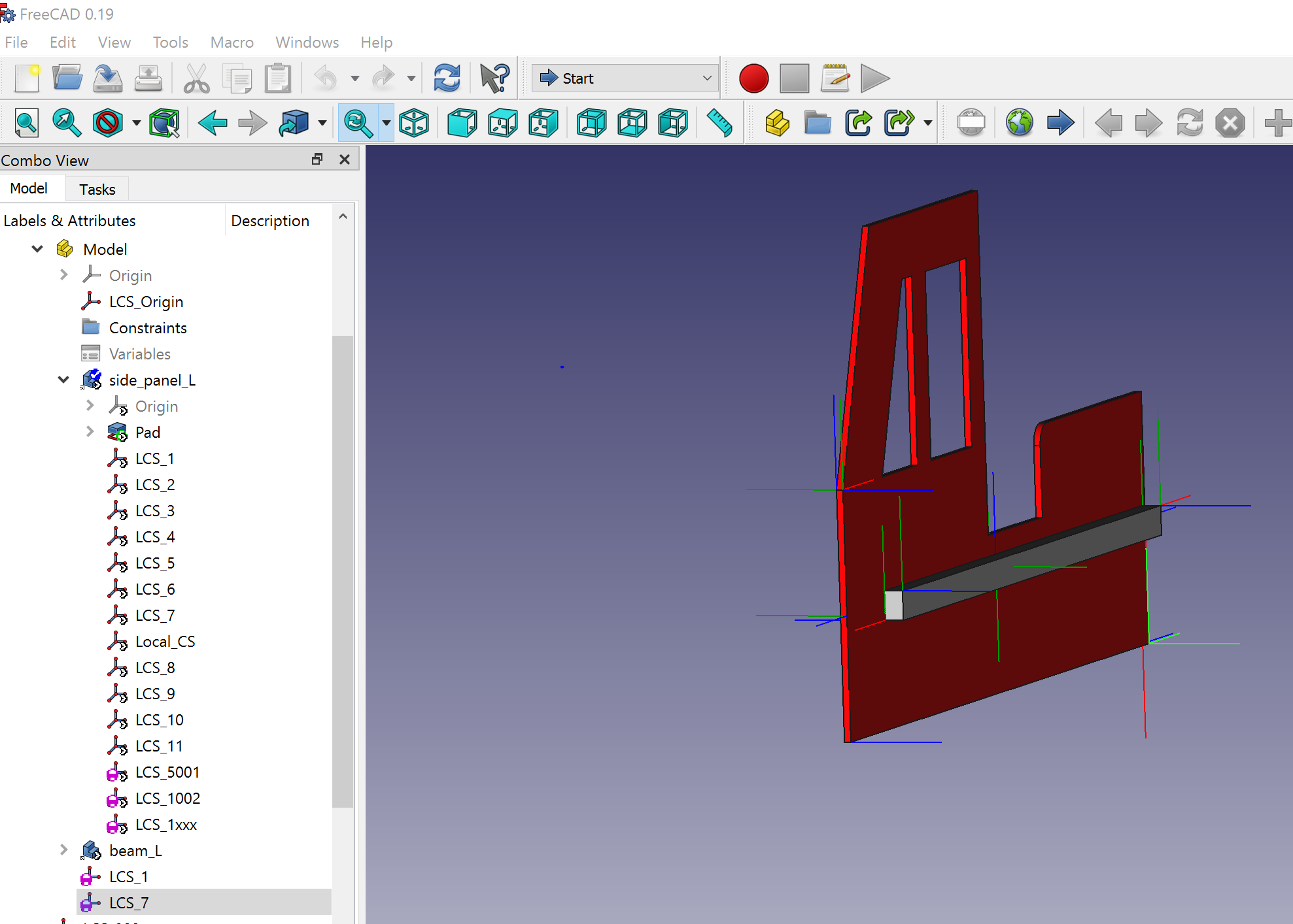
The picture shows my side panel that I build. In the model tree on the bottom you see LCS_7 with a purple circle in it (I think this is a global coordinate system). This one works, so it can be done, but no idea how I got it there so I can’t reproduce it.
Please tell which Assembly addon you are talking about, preferably in the subjetc, and give a link to the tutorial. If it is a video tutorial give the time code as well.
The command you’re looking for is “Import Datum object” : this one, when a datum is selected (in the tree, not in the 3D window !), creates another datum of the same type one level above, and sets the Placement property of this newly created datum to that of the initially selected datum (by the ExpressionEngine). This newly created datum is native in the container above (it’s not an App::Link to the original datum) and thus can be used to attach any other object to it, and its position will always match that of the original datum in the part in the sub-assembly. Even when modifying the parameters of the part and/or sub-assembly.
It allows to build truly parametric nested assemblies to any level.
The stability and the performance of large nested assemblies are uncertain.
Thanks heaps guys! And will definitely put more info in the post next time. Tried the import datum, and it works .
I do have another question though, hope you guys know the answer to that as well. As you can see in the picture I posted, that assembly is a side panel (building a toddler fire truck bed) which I need for the assembly of the bed. So I need to somehow mirror this assembly so I can put it in the bed assembly.
Do you guys know how I can mirror the full assembly? (turning doesn’t work as the beam is then on the outside instead of the inside)
There’s nothing particularly special about this newly created datum, right? So far, I haven’t used this function at all to connect sub-assemblies. What I’ve done is make sure the sub-assembly has an appropriate LCS in its model level, and choose that as the connecting point when I link the sub-assembly. And I’ll link this LCS to an appropriate LCS in the main assembly. So if I’m understanding this right, that’s just a manual way of doing an ‘import datum object’ right? Is there any differences to using this function that I’m not aware of? If there is, I hope to see it documented better so that we can understand what the best practice is supposed to be.