The best advice I can give you is to experiment, experiment, experiment. Create a sketch in any plane with a circle at the origin. Create another sketch in any plane with an arbitrary straight line and circle or arc. Now, try to attach the first sketch to the second sketch in different locations and various ways with all of the different modes until you understand the process and the attachment implications. Try also with a helix. And, do not overlook the attachment offset properties. Do that about 10 times and you’ll start to get it.
The best documentation is perhaps the attachment map mode dialog box itself. Work your way top to bottom after selecting the 2nd sketch edge or vertex for the 1st sketch attachment. Note that the attachment offset is related to the sketch XYZ axes not the global coordinate system ( a bit confusing).
You will probably never need about 80% of the modes, but if you do, you will be glad they are there.
Attachment is a very sophisticated tool so it takes some practice, especially for us pensioners.
ppemawm - I’ll give your suggestions a try and see if I can make some headway. I’m convinced that if I can master this attachment stuff FC will really open up for me. Thanks.
I’ve looked at your files and can’t figure out what point_1 and point_2 are.
For fun I tried to make another version of the bed with Assembly 4. It was a good exercise for me especially since I tried to link all the LCS only to the sketches.
Everything is configured by the MasterSketch of which I attach a photo explaining the dimensions that can be modified.
If anyone is ever interested in explanations, I will complete the documentation especially regarding LCS.
Hey all,
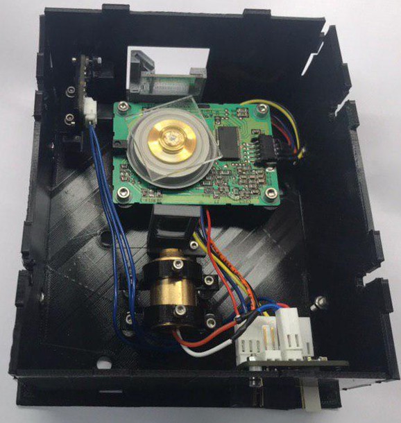
I am just here to say I am quite happy with the assembly 4 workbench. I designed an open hardware laser scanner in Freecad, Assembly 4.
The result can be seen in the image below
.
The files can be found here https://github.com/hstarmans/hexastorm_design. An earlier design has also been build. It is a somewhat older image and you should notice some differences
The scanner has its own blog on https://hackaday.io/project/21933-open-hardware-fast-high-resolution-laser. The PCBs are designed in Kicad see, https://github.com/hstarmans/firestarter. The laser can be controlled with an ice40 FPGA using yosys. The code has been programmed in python using migen https://github.com/hstarmans/hexastorm
For me freecad with the extensions; assembly 4, fasteners and KicadStepUp have been very helpfull. They allow me to bring the open hardware prism scanner to the next level.
The only issue I sometimes encountered is that if I select the wrong part and move screws around, the part can break if I do something wrong with the selection.
Nice work, but I think you have overly complicated your life.
I don’t have the time to do it now, but you could try the following:
in a new file, create an Asm4 Model
in that same file, create 3 bodies Leg, Long_Side, Short_Side
create variables Length, Width, Height …
draw the 3 parts in PartDesign using the Variables where needed
create a MasterSketch in the Asm4 Model, and draw a rectangle using Length and Width from Variables
create another MasterSketch, import the previous rectangle, and draw some lines that will define the position of the legs
(if you do it all in 1 sketch, you have a good chance to run into the toponaming issue)
create all necessary LCS, and attach them to the 2 MasterSketches
import de 3 bodies and place them onto the LCS
change the variables and check that everything moves as expected
ppemawm, what do you think, how would you do this ?
I would probably do the same as you suggest if, when you say “import the previous rectangle”, you mean Sketcher > carboncopy or external reference, and by “import 3 bodies” you mean assemble the links?
I think it’s a bit of a shame to use Asm4 for such a project. It’s a bit like using a power hammer to smash a fly.
On the other hand, I thought of the second solution as an exercise allowing me to understand the sub-assembly as well as giving simple examples of LCS positioning and “importing”.
Here is a new solution for the bed following Zolko’s suggestion.
Compared to what Zolko suggested I only used one sketch because I do not understand where the topological naming issue could come from.
On the other hand, I had some problems with this sketch because I had initially used length, width and thickness of the wood. And when I changed the dimensions this thickeness “jumped” from the inside to the outside causing problems. This is why I then gave the inside and outside dimensions of the main rectangle (for example width and width -2 * thickness).
With this method I had to introduce eight LCS for the legs, that’s a lot. Was there a way to use transformations (symetry, rotation) on links in order to avoid to use such a lot of LCS ?
If wanted and if you find that interesting, I can try to write something in order to explain/compare the three methods.
Hi Zolko,
What do you think about making the ‘move/attach a part’ function keep the attachments that are already selected for a part? I’m finding that I often use this when I need to make a small attachment adjustment, say in xyz position/rotation, but I don’t need to reattach it somewhere else. Right now, it resets the attachments so you have to go in an remake them. It would save a lot of clicks if it didn’t do this. And if you did want to reattach it, it would be the same amount of clicks anyway since you’re changing the attachment.
I just highlighted on a simple example a problem which slowed down my animations as well as the reloading of files.
It is just a pierced pad that rotates around its axis (I made the pocket in a second sketch for the needs of the demonstration)
In the first file Simple_Ex_01, the basic Sketch is defined with an explicit length of 50mm for the side. If it is rotated by varying from 0 to 360 in steps of 1, the speed is correct.
In the Simple_Ex_02 file I introduced a variable of value 50 and I use this variable to define the length of the side of the Sketch. This file was saved before any animation.
If I then do the same animation as before, it is horribly slow.
But especially when I save the same project (after the animation) in Simple_Ex_03 its size has drastically increased. And so it becomes very slow to load.
Is it bad (forbidden) to use such a variable of the ?
Nevermind about the issue of not having the LCS selected when trying to move them. This seems to be an issue only in realthunder’s linkstage 3 version. When using main .19, it works fine.
In YouTube videos I found they simply type into the formula field “Variables.” but this doesn’t work for me:
Could anybody help me please?
I have 4 parts that are placed according to the LCS so I want to rotate the LCS and all parts will rotate too. When I change the rotation angle manually, it works as i need it, the only issue is that I cannot animate the angle.
So I found now a way to animate but would like to understand why I cannot access the variable to any formula I want.
I am pretty sure this happens because the objects inside the linked body only have access to data inside the body which means that the variables stored in the assembly can’t be accessed by the formula editor when you try to modify the attachment angle of the LCS. I think you can’t access the variables inside the assembly from inside the linked body in order to avoid cyclic dependencies.
I’ve got a question. Maybe it sounds stupid, but here it goes :
Can I attach a subassembly/part by more than one attachment point?
Scenario: I’m creating a suspension system. I’ve got a rear shock that consists of 2 parts. the main body and the moving rod. Now I’ve created an assembly file that combines both of them, let’s call it shock assembly. It has a sketch that is used for the movement of the parts (and the sketch also limits max positions). So far it works great, no problem. But…
Now I want to add this shock assembly to be part of a bigger assembly. The bigger assembly contains the two body parts that are dampened by the shock. So this bigger assembly consists of part A and part B. each has a point where the shock should be attached.
Attaching the shock to part A is quite easy of course. (lower shock LCS to part A LCS). But how do I now attach upper shock LCS to part B LCS? In an ideal world keeping the constraints of shock assembly (min/max).
Or is this not possible?
Do I need to embedd main body and rod separatly in the “master assembly”? And define the shock sliding and min/max limits in the master assembly? And do this again for each and every “master assembly” that is using this shock?
Thank you very much for your answer,
Kind regards,
Martin Schmidt
stats:
OS: Windows 10 (10.0)
Word size of OS: 64-bit
Word size of FreeCAD: 64-bit
Version: 0.19.23323 (Git)
Build type: Release
Branch: master
Hash: 512d5c6141aec52b6eecc67370336a28fde862a6
Python version: 3.8.6
Qt version: 5.12.5
Coin version: 4.0.0
OCC version: 7.4.0
Locale: English/Germany (en_DE)
It’s not a stupid question, but it’s not possible today: Assmebly4 needs a real 3D solver for that, which it’s doesn’t have yet. There are plans and discussion about it (see thread Discussion: Merging A2plus and Assembly4 for example).
Exactly: you can access data in linked parts from within the assembly, but not the other way around. If you still wan to do it, you need to trick the system: include the same file in both the assembly and the sub-assembly, and store the common data in that common file. I tried and it works, but I don’t know how robust that is.